
LSS - Configuration Software
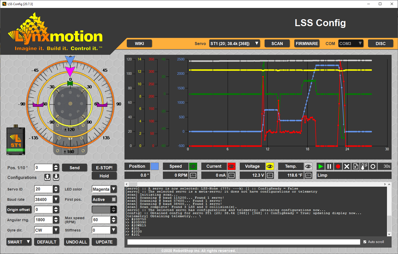

Table of Contents
Description
The LSS Configuration software ("LSS Config" for short) is intended to provide easy access to the main features and functionality of the Lynxmotion Smart Servo Motors, as well as providing access to firmware updates.
NOTE: The software can be connected to multiple servos, but the interface can only control one at any time. The servo(s) must be powered correctly and in serial mode. Should your servo(s) NOT be in serial mode, please refer to the button menu.
Features
Connection


The headers above show the three main states (from top to bottom):
- Before a connection is made
- After a connection, before a scan
- After a scan with a LSS selected
The header includes (left to right):
- COM port selection
- CONNECT / DISCONNECT (toggle ON / OFF)
- SCAN: (popup) scans the bus for all available servo motors
- SERVO LIST: Servo selected via the dropdown menu
- FIRMWARE: (popup) used to update servo's firmware
- WIKI (link to the LSS Config guide on the Lynxmotion Wiki)
COM Port
Connection to the servo is done automatically via any properly installed USB to serial interface like the LSS Adapter board. Once the servo is powered and properly connected to the computer, the COM port should appear in the COM port list. Ensure the board is recognized by the computer and if not, install the proper drivers. If you have multiple communication ports active, go to Windows -> Device Manager to determine which is appropriate for the USB to serial adapter you are using. Click CONNECT to connect to the servo. If you wish to change the COM port selected you must disconnect, select the correct COM port and reconnect.
If you are not sure which COM port to select, in Windows, go to Device Manager -> Ports (COM & LPT) and select the port associated with the USB to serial device. If it is still not clear which is the proper COM port, simply disconnect and reconnec the USB cable with Device Manager open. The proper COM port will disapear (when disconnecting the USB cable) and reappear (when connecting the USB cable).
Scan

The next step once the COM port has been selected is to scan the port. The software can send commands to (and listen for a reply from) all servo IDs (0 to 250) at all standard baud rates on the selected COM port. In the pop-up, select the baud rates which you would like to scan. You press the ALL button to select all baud rates, press the individual check boxes to toggle each select or press the << button to select only the corresponding baud rate, deselecting all others. You may also limit the IDs to scan for. When in doubt, leave all baud rates selected.
Once you press OK, the scan will start by turning off the LED of all servos on the selected baud rates (#254LED0\r). Then, each selected baud rate is scanned for servos. The command line interface will include messages for all servos found (or not found) at each baud rate, as well as any conflicts discovered (two or more LSS at the same location). In this case, a location is defined as a baud rate and ID pair.
This process will take a few seconds and once completed, a list of all available servos with which the software was able to communicate will appear in the list next to "Servo" (in the top orange Connection field of the interface) as a drop-down. All servos correctly identified on the bus will have their LED turn green (session specific as opposed to configured) to indicate no conflict. If two or more servos have the same ID, those servo's LED will turn red for that session, indicating an issue or overlap in IDs. To resolve this, you will need to change the ID of those servos to be distinct (they will need to be connected individually/separately from the other conflicting servos).
GREEN LED: No Conflict
RED LED: Conflict Found
Note that these LED colors are SESSION specific (as opposed to configured). The LED color listed under Configurations will remain the user choice (OFF by default).
Servo
The scan provides a list of all servos which have been detected on the bus and lists the following choices in the drop-down. Note that the last servo in the list is automatically selected for convenience.
LSS-None (???; ---k)
This first option is used only when a servo ("???" to signify "unknown servo") cannot be reached via the LSS Config software and needs to be manually set to bootloader mode via the button menu in order to re-flash the firmware. The telemetry graph and configurations are all greyed out when this is selected. Once the servo has been set manually to bootloader mode, select this option and go through the firmware update procedure. This normally only needs to be done as a "last resort".
Note: You can use this special firmware recovery function with 2 or more servos simultaneously. Just make sure they are all in bootloader mode before stating the firmware update using this option.
LSS-All (254; ---k)
This option allows actions that affect all detected servos in the list after a successful scan. Since there is no particular servo being monitored, the telemetry graph and configurations are all greyed out. This is used to send the same firmware update to all detected servos on the bus or to send the same action command via the command line interface described below.
The drop-down list will be populated with all servos which the software has found on the bus, indicating their servo model, ID and firmware version. Each servo will then be listed in the following format:
ST1 (0;115.2k [368])
The servo model is displayed first (ST1, HS1, HT1), followed by its ID, the baud rate to which it has been st (ex. 115200, or 115.2k) and its firmware version in rectangular brackets. Selecting a servo from the list will allow the software to communicate with it.
Firmware Update
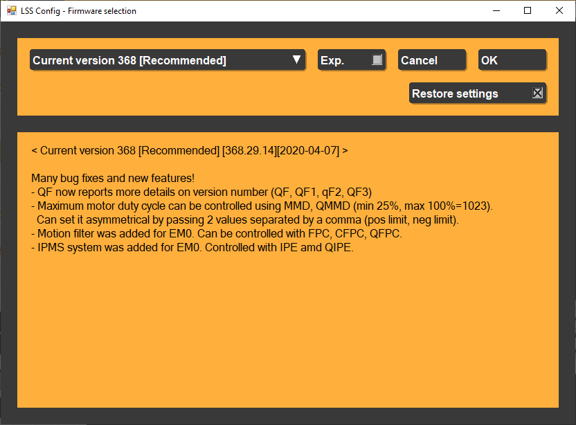
The firmware update option is a popup which includes:
- Firmware version selection in a dropdown list, including the current recommended version
- Experimental firmware (optional)
- Cancel firmware update
- OK to continue firmware update
- Checkbox to try to save & restore the settings (config)
- Notes regarding the selected firmware
The LSS Config serves as the main software used to update the servo's onboard firmware. An internet connection is needed in order for the software to check if an online update is available and obtain a copy. When checked, the Exp. button will allow experimental versions of the firmware to be displayed in the list. It also allows to load a firmware directly from a local file.
Following this pop-up your servo will be restarted (unless already in bootloader mode, see LSS-None above) and a progress bar will be displayed in the command line. Do not disconnect the servo during a firmware update. If the process does get interrupted, you can still upload firmware to the LSS by going into bootloader mode by holding the button at power up.
NOTE: Before assembling the servos as part of a robot, check to see if there is a firmware update available.
Servo Control
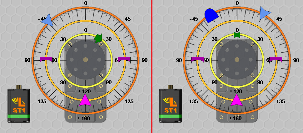
The servo control section allows you to visually move the servo and change a variety of parameters, including:
 Position: pale blue caret
 Origin offset: magenta caret
 Angular range: magenta square carets
 RPM: green arrow / indicator
 Initial position: dark blue caret
At the lower left the servo model and the LED color (session value) are shown.
To change a value, simple use the left mouse button to hold and drag the relevant caret around its ring. Letting go of the left mouse button will update the value right away. While holding the left mouse button you can also press the right mouse button to cancel the current change to that caret (happens after right mouse click and then letting go of the left mouse button).
If the caret moved is position, this will send a position command in tenths of degrees right away to the servo (#[id]D[pos]\r).
If the caret moved is first position, offset or angular range then it will update the appropiate configuration (see below for details), pending an update confirmation.
The speed caret cannot be moved directly; it only serves only as a display of the current speed.
Configurations
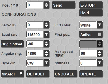
Upon connection, the software will read all configuration values and update the values in the "configurations" section. Visit the LSS - Communication Protocol page for more information about commands, actions and configurations.
Changing the values will not affect the session. Values which have been changed will have a yellow background. The values which can be entered are restricted to what the servo can accept; for example, servo IDs must be below 250.
Each command is associated with the following protocol. Additional details for each can be found on the LSS Communication Protocol page.
| Field | Command | Update? |
| Pos 1/10 & Send | D (position in 1/10 degrees) | No |
| E-STOP | L (limp) | No |
| Hold | H (Halt & Hold) | No |
| Servo ID | CID (Configure servo ID) | Yes |
| Baud Rate | CB (Configure Baud rate) | Yes |
| Origin Offset | CO (Configure Origin Offset) | Yes |
| Angular Rng | CAR (Configure Angular Range) | Yes |
| Gyre Dir | CG (Configure Gyre direction) | Yes |
| LED Color | CLED (Configure LED) | Yes |
| First Pos. & Active & Value: | CFP (Configure First Position), toggle active & input value | Yes |
| Max Speed (RPM) | CSD (Configure maximum Speed in Degrees) | Yes |
| Stiffness | CAH (Configure Angular Holding stiffness) | Yes |
UPDATE Pressing this button will write all values to EEPROM, changing the configurations, and reverting all background colors to white.
UNDO ALL is a shortcut button which reverts all changes made which have not been written to EEPROM.
SMART / RC POS / RC WHL: This is a shortcut to change the servo's mode (LSS Smart Serial / RC PWM Position / RC PWM Wheel). IMPORTANT NOTE: Should you select either of the two RC modes, the LSS Config software will no longer be able to communicate with the servo. You must use the button menu to return to LSS serial mode (hold the button, release, press twice).
Telemetry Graph
The sensor graphing feature of the software allows you to select, display and record, with respect to time, the output from all of the servo's sensors.
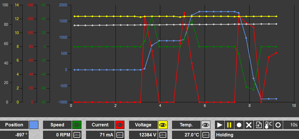
x-Axis: seconds
- Position: blue
- Speed: green
- Current: red
- Voltage: yellow
- Temperature: gray
 | Sensor Feedback Visibility (ON) |  | Sensor Feedback Visibility (OFF) |
 | Query value (ON) |  | Query value (OFF) |
| Graphing (OFF) | Graphing (ON) | ||
| Pause queries (OFF) | Pause Queries (ON) | ||
| Record Sensor Queries (Not Recording) | Record Sensor Queries (Recording) | ||
| Reset Graph | |||
| Export recording to .csv (comma separated values) | Export popup appears providing three options: 1) Export only recorded data ("YES") 2) Export all data (click "NO") 3) Cancel export | ||
 | Temperature Units (Celcius) |  | Temperature Units (Fahrenheit) |
 | Marker Icon Style (Circle) |   | Marker Icon Style (Diamond / Square) |
 | Time Window (10s) |
| Time Window (30s / 60s / 300s / Total) |


Note that when multiple servos are connected, and the user changes between servos, the telemetry graph is not cleared (use the reset graph button).
Occasionally the telemetry values may all simultaneously drop to zero for one reading, or skip a point due to other processes taking priority.
Command line
The command line interface both allows you to communicate directly with an individual servo, send commands to it and view replies to queries. When "LSS-All (254; ---k)" is selected in the list of servos, the command line is used to send the same action or configuration command to all detected servos. For example, typing D1800 and pressing enter will send that same position command to each of the detected servos.
Within the command interface, you might see the following:
| >> | Command sent to the servo |
| << | Reply from the servo |
| INF :: | Information |
| [bootloader] | Information specific to bootloader mode & firmware updates |
| ]] | Failure |
 | Configuration command redirected to config interface (left hand side) |
The command line also auto-completes each command by automatically inserting "#[id]" before each command for you. Therefore, you only need to type the command itself, such as "D1000" and press [enter]. For example, rather than typing #4D230<cr>, you need only type D230 and the software will automatically add #4 & \r.
Left clicking a line within the command prompt and then right clicking using your mouse highlights that line in a green border and allows it to be copied to the clipboard and pasted into another document. Scrolling is opposite that to browser navigation.
The mouse wheel can be used to scroll and the holding the middle mouse button down allows for panning over the command line area (useful if text extends to the right). There are also two scrolling bars that can be used with the left mouse button as normal for panning the command line view.