3DoF Lexan C Leg Assembly Instructions
| "C" Leg Assembly Instructions.
Updated 12/20/2011 Safety first! Wear eye protection and never touch a powered robot! Note: Do not use Loctite or thread locks on the assembly. They are not necessary and may cause damage to the
Lexan. |
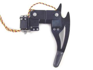
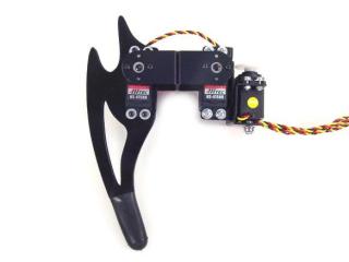 Image of completed Robot's Right Leg. |
||||||||
| Lexan Preparation. The lexan pieces have a protective covering that needs to be removed before assembly. When the laser cuts, the covering melts into the cut edge which can make removal difficult. If you gently scrape the cut edge with a flat blade screwdriver, the covering can easily be lifted and peeled off. On smaller pieces the coverings can be more difficult to remove. If you have trouble you can gently scrape the cut edge, then use duct tape to lift the covering off. For further information on lexan, see this page. |
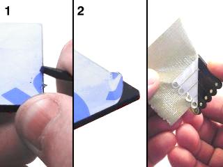 Lexan Preparation. |
||||||||
| Step 1. Push the servo in through the lexan as shown. (Note, this is for a robot's right leg. You will need to mirror these steps for the left legs.) |
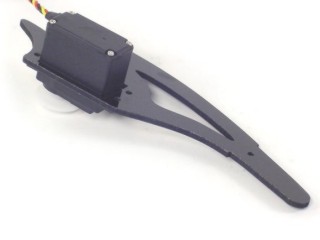 Figure 1. |
||||||||
| Step 2. Push the spacer lexan over the servo as shown. |
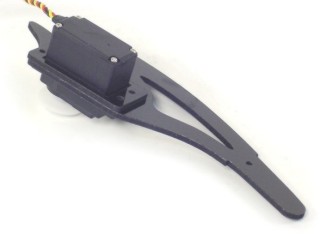 Figure 2. |
||||||||
| Step 3. Push the final lexan piece over the servo as shown. |
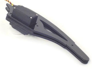 Figure 3. |
||||||||
| Step 4. Use the 4-40 x 3/4" hex screws with washers and nylon-insert lock nuts to secure the servo.
|
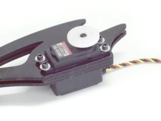 Figure 4. |
||||||||
| Step 5. Connect the bottom of the leg with a screw and a nut.
|
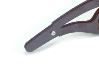 Figure 5. |
||||||||
| Step 6. You might want to use sandpaper to smooth off the edges of the bottom of the foot. It will be easier on the rubber end cap if you do. |
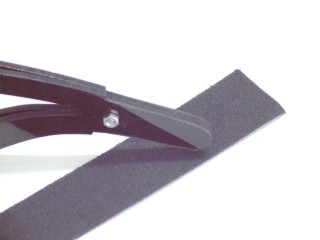 Figure 6. |
||||||||
| Step 7. Push the rubber end cap onto the end of the leg. It will come up over the screw and nut. |
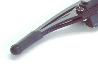 Figure 7. |
||||||||
|
|
|||||||||
| Step 8. Peel the white cover off of the tape and press the tape onto the hinge as shown. |
 Figure 8. |
||||||||
| Step 9. Attach the servo hinge as shown. Press it down firmly to ensure good contact. |
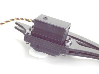 Figure 9. |
||||||||
|
|
|||||||||
| Step 10. Attach a ball bearing to the multi-purpose bracket as shown. Refer to Figure 10-1 for detailed information. Note, this ball bearing is part of the chassis kit or "C" bracket, if used.
|
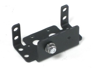 Figure 10-2. |
||||||||
| Step 11. Attach the two multi-purpose brackets as shown, using two 2-56 x .250" screws and 2-56 nuts.
|
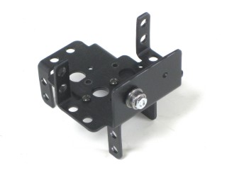 Figure 11. |
||||||||
|
|
|||||||||
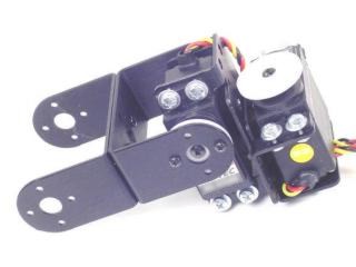
| Step 12. Attach the two "C" brackets as shown, using two 2-56 x .250" screws and 2-56 nuts.
|
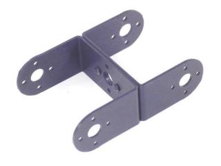 Figure 12. |
||||||||
|
|
|||||||||
| Step 13. Attach "C" bracket to the multi-purpose bracket as shown. Refer to Figure 13-1 for detailed information.
|
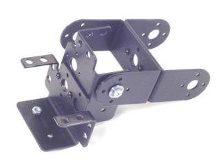 Figure 13-2. |
||||||||
|
|
|||||||||
| Step 14. Attach the servo as shown, using either the snap rivet fasteners or 3mm hardware (shown). Make sure to route the servo wire as shown. |
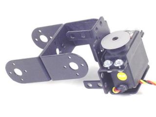 Figure 14. |
||||||||
|
|
|||||||||
| Step 15. Attach the servo as shown, using either the snap rivet fasteners or 3mm hardware (shown). Make sure to route the servo wire as shown. |
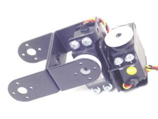 Figure 15. |
||||||||
|
|
|||||||||
| Step 16. Attach the servo to the "C" bracket using the #2 tapping screws and the diagram below. Make sure that the servo is centered before attaching to the "C" bracket.
|
|
||||||||
| Step 17. Attach the servo to the "C" bracket using the #2 tapping screws and the diagram below. Make sure that the servo is centered before attaching to the "C" bracket.
|
|
||||||||
|
|
|||||||||
| Step 18. Attach the "C" bracket to the servo hinge as shown. Refer to Figure 18-1 for detailed information. Make sure to route the servo wire as shown. Leave enough slack for the leg to be able to freely move without pulling on the servo wire.
You can now move on to the body assembly instructions. |
|
||||||||