
Phoenix 3DoF Assembly Instructions v5.0
Phoenix Assembly Instructions Rev. 5
Updated July 12, 2010
Safety first! Wear eye protection and never touch a powered robot!
The purpose of this guide is to construct the chassis, attach the legs, and install the electronics. As long as the servo horns have not been removed from the servos, you do not have to center them during the assembly process.
Note: Two screws are included for attaching panels to servo horns. You may want to use four screws, as shown in some images. The 2-56 x 1/4" screws are available separately. Metal servo horns are an additional option.
Important! These instructions are for the robot's right legs. You will need to mirror these instructions and build three left legs as well.
Place an HS-645 servo against a tibia (lower) leg piece as shown, and secure in place using the hardware specified in Figure 1-1.
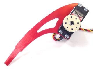 Figure 1-2.
Attach a ball bearing to the multi-purpose bracket as shown. Refer to Figure 2-1 for detailed information.
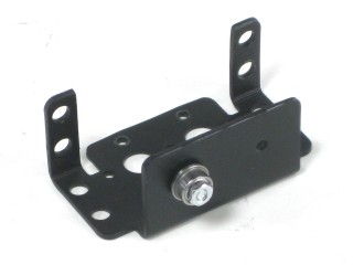 Figure 2-2.
Attach the two multi-purpose brackets as shown, using two 2-56 x .250" screws and 2-56 nuts.
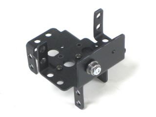 Figure 3.
Attach servos into the brackets as shown in Figure 4-2 using the hardware specified in Figure 4-1. Use an HS-475 servo in the multi-purpose bracket with the ball bearing installed, and an HS-645 servo in the other.
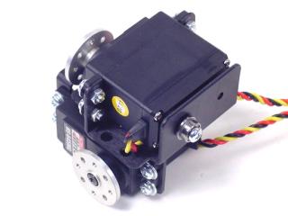 Figure 4-2.
Attach a leg femur (upper) piece as shown. If you are using nylon servo horns, use #2 tapping screws. If you are using aluminum servo horns, use 2-56 screws.
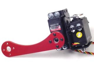 Figure 5.
Attach the two leg assemblies together as shown. If using nylon servo horns, use #2 tapping screws. If using aluminum servo horns, use 2-56 screws.
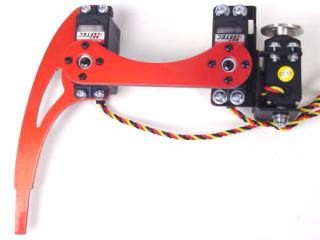 Figure 6.
Use the 4-40 x 3/8" hex socket screws to attach the spacers to the underside of the top panel. The panel is symmetrical — whichever side you attach the hex spacers to will be the inside of the robot.
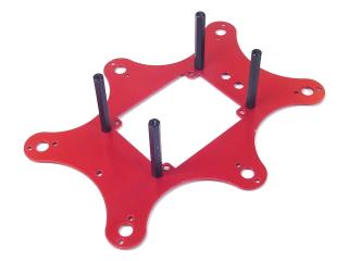 Figure 7.
Use the 4-40 x 3/8" hex socket screws to attach the bottom of the robot to the spacers.
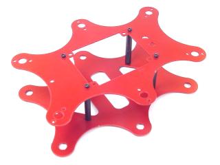 Figure 8.
Configure the SSC-32 for 115.2 kbaud and DB9 communication, with the VS2=VS1 jumper installed. Remove the VL=VS jumper. Consult the SSC-32 manual if needed. Attach the wiring harness to VS1. Connect 8" of 24AWG wire (not included) AND the 9V battery clip to VL to power the electronics. Make sure red wires go to (+) and black wires go to (−). Put electrical tape on the free wire end for now. Using four 4-40 x 3/8" hex socket screws, attach the 1.0" hex spacers to the board as shown.
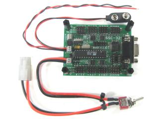 Figure 9.
Schematic. Double check your connections against the schematic below.
| Servo Letter Definitions | ||
|---|---|---|
| Left Right |
Rear Middle Front |
Knee Vertical Horizontal |
Schematic 3-1.
Slip the SSC-32 in through the hole in the top of the robot and use four 4-40 x 3/8" hex socket screws to attach the board as shown. Make sure the DB9 port is at the front of the robot, opposite the power switch hole! This ensures you can easily plug in the servo cables. Install the power switch in the power switch hole at the rear of the robot.
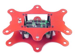 Figure 10.
Install all the legs. Refer to Figure 11 for clarification.
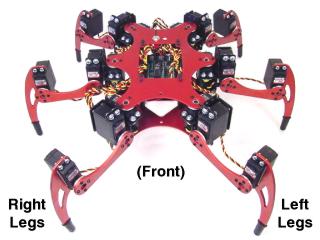 Figure 11.
Plug the servos into the SSC-32 as illustrated in Figure 12. Simply plug in the servo associated with the function to the corresponding pin. If oriented correctly, the I/O port (group of four pins) will be closest to its corresponding leg.
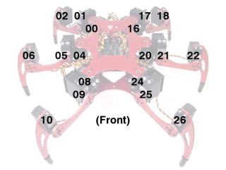 Figure 12.
Remove the servo horn screw on the knee servo enough to remove the horn. Rotate the tip of the foot in toward the body by 1 click (15°), then push it back into place and tighten the screw.
Do this for all 6 legs.
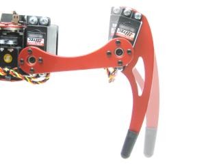 Figure 13.
Route the servo wires as shown in Figure 14. Make sure you leave enough slack to fully extend the legs! This is very important.
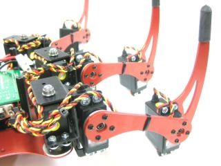 Figure 14.
This completes the mechanical assembly.
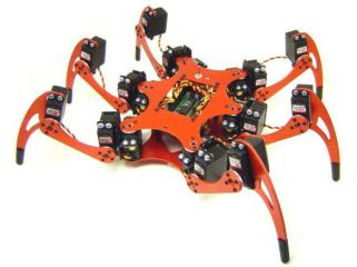 Figure 15.