Lynx Arm Turntable Assembly Instructions v2.0
Last modified by Eric Nantel on 2023/04/04 08:09
| Lynx
Arm Turntable Assembly Instructions version 2
Updated 08/03/2004 Safety first! Wear eye protection and never touch a powered robot! Note: Do not use Loctite or thread locks on the assembly. They are not necessary and may cause damage to the Lexan. |
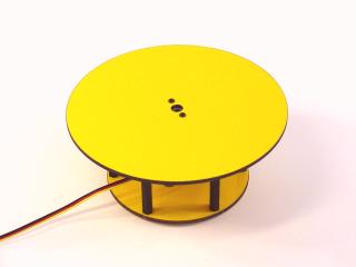 Image of turntable. |
| Step
1. Install the servo into the top panel using four of the rivet fasteners. The servo should go in through the bottom of the Lexan panel. 4 x |
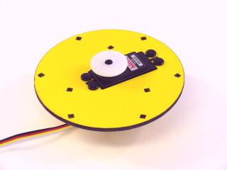 Figure 1. |
| Step
2. Install the .375" hex spacers using three .625" 4-40 nylon screws and three acorn nuts. These are the bearing surfaces for the turntable rotate panel. Tighten these down snugly. 3 x |
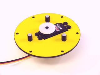 Figure 2. |
| Step
3. Install the 1.500" hex standoffs using six .375" 4-40 screws as shown. Tighten them down snugly. 6 x |
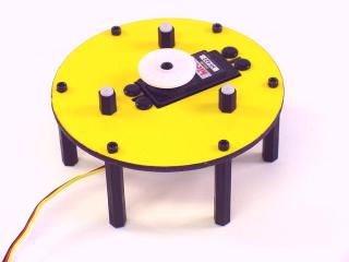 Figure 3. |
| Step
4. Install the bottom panel onto the turntable assembly using six .375" 4-40 screws. Tighten these down snugly. 6 x |
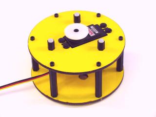 Figure 4. |
| Step
5. To maintain compatibility with our program, the turntable rotate servo has to be mechanically aligned. To do this move the servo to its center of rotation using the Bot Board, or your servo controller or microcontroller. Consult your electronics documentation for help with this step. Note, centering a servo simply requires generating a 1.5mS positive going pulse that repeats every 20mS. For the Bot Board, check the Tutorial page for a step-by-step guide. |
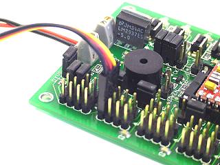 Figure 5. |
| Step
6. While the servo is centered, install the rotating panel as illustrated. Use two #2 .250 tapping screws for this step. The turntable can rotate +/- 90 degrees from its mid position for a total of 180 degrees of rotation. 2 x |
Figure 6. |
 3 x
3 x