Mechanical Dampener Assembly v2.0
Last modified by Eric Nantel on 2024/07/03 09:21
| Mechanical Dampener Assembly, Ver 2.0
Updated 12/21/2011 Safety first! Wear eye protection and never touch a powered robot! |
 Mechanical Dampener. |
||||
| Lexan Preparation. The lexan pieces have a protective covering that needs to be removed before assembly. When the laser cuts, the covering melts into the cut edge which can make removal difficult. If you gently scrape the cut edge with a flat blade screwdriver, the covering can easily be lifted and peeled off. On smaller pieces the coverings can be more difficult to remove. If you have trouble you can gently scrape the cut edge, then use duct tape to lift the covering off. For further information on lexan, see this page. |
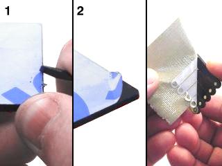 Lexan Preparation. |
||||
|
|
|||||
| Step 1. Insert the 4-40 x .5" Phillips head screw through the hold in the multi-purpose bracket as shown. Secure with a steel nut.
|
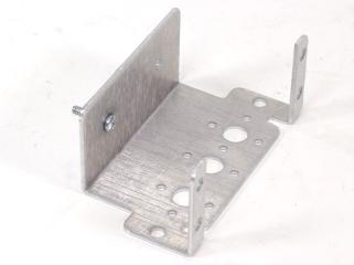 Figure 1. |
||||
| Step 2. Sandwich the "C" bracket between the two lexan discs as shown. Make sure the disc with the large center hole is on the inside, and the disc with the small center hole is on the outside. Use two 2-56 x .250" machine screws to hold them in place. Be careful not to over tighten them.
|
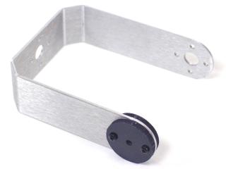 Figure 2. |
||||
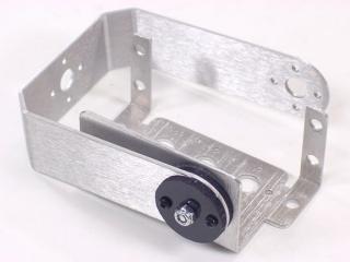
| Step 3. Attach the "C" bracket to the multi-purpose bracket as shown, using a nylon insert lock nut. Tighten this down fully, then back off in 1/4 turn increments, until the joint can move but hold position. There should be enough friction to add mechanical dampening to the axis, without over-stressing the servo. If you find it is too tight or too loose, it can be adjusted later.
|
Figure 3-2. |
||||
|
|
|||||
| Step 4. Attach a servo into the multi-purpose bracket as shown in Figure 4-2 using the hardware specified in Figure 4-1.
|
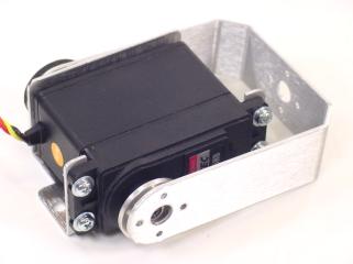 Figure 4-2. |
||||
|
|
|||||
| Step 5. Secure the "C" bracket to the servo horn as shown, using two 2-56 x .250" Phillips head screws.
|
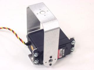 Figure 5-2. |
||||