
Quadruped QBK-02 Symmetric Robot Kit Assembly Instructions Rev. 1
QBK-02 Symmetric Quadruped Robot Kit Assembly Guide — Rev. 1
Updated December 2014
Safety first! Wear eye protection and never touch a powered robot!
Both top and bottom body plates are identical. The guide shows the optional PS2 receiver and mount (BotBoarduino version only). Available kit configurations:
- SQ3 with BotBoarduino + SSC-32
- SQ3 with BotBoarduino + SSC-32U
- SQ3 with SSC-32 + Bluetooth (FlowBotics)
- SQ3 with SSC-32U + Bluetooth (FlowBotics)
Note: Follow each step for your specific kit — connections and configuration differ. Loctite may be used on aluminum components but never on Lexan or plastic parts.
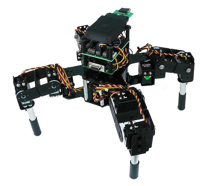
Completed QBK-02 (with optional PS2 receiver and mount).
Remove the protective covering from all Lexan pieces before assembly. The laser cutting process melts the covering into the cut edge. Gently scrape the cut edge with a flat blade screwdriver to lift and peel the covering off. On smaller pieces, use duct tape after scraping. For more info on Lexan, see this page.
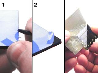 Lexan preparation.
Before assembly, read the appropriate user guides for your kit:
- SSC-32 User Guide (if you have the SSC-32)
- SSC-32U User Guide (if you have the SSC-32U)
- BotBoarduino User Guide (if your kit includes a BotBoarduino)
The QBK-02 uses the Arduino software from www.arduino.cc. This guide does not teach the Arduino programming language.
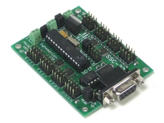 Figure 1 (SSC-32 shown as example).
The SSC-32 (not SSC-32U) and BotBoarduino kits require a separate 9V battery. Place the small black rivet through the 9V metal clip and push it down through one of the two inner holes as shown. Either side works. This becomes the bottom plate.
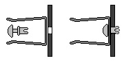
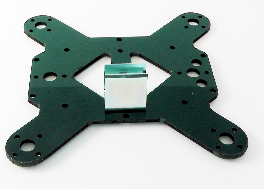 Figure 2 (SSC-32 and/or BotBoarduino).
Use six 4-40 x 1/4" hex socket screws to attach the long aluminum spacers to the bottom body plate. The SSC-32U version does not require the 9V clip from Step 2.
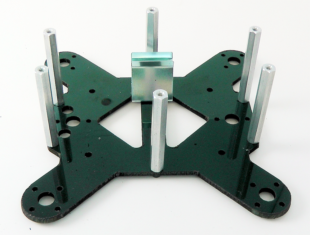 Figure 3a (SSC-32 and/or BotBoarduino).
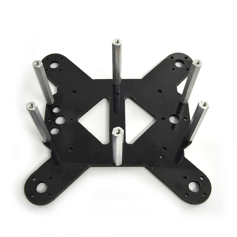 Figure 3b (SSC-32U alone).
Use the second (top) plate for this step. Use four 4-40 x 1/4" hex socket screws to attach the plastic spacers.
Option A — BotBoarduino kits: Use 1/4" M/F plastic spacers (electronics will be stacked). Also connect the 9V wiring harness and servo battery harness to the top plate — either switch hole works.
Option B — SSC-32 or SSC-32U alone (FlowBotics): Use 1/4" F/F plastic spacers (no stacking above servo controller). Connect only the battery harness to the top plate. The 9V harness is not needed for the SSC-32U.
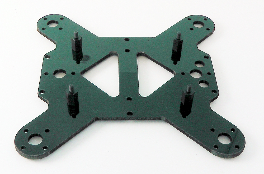 Figure 4a (BotBoarduino — M/F spacer).
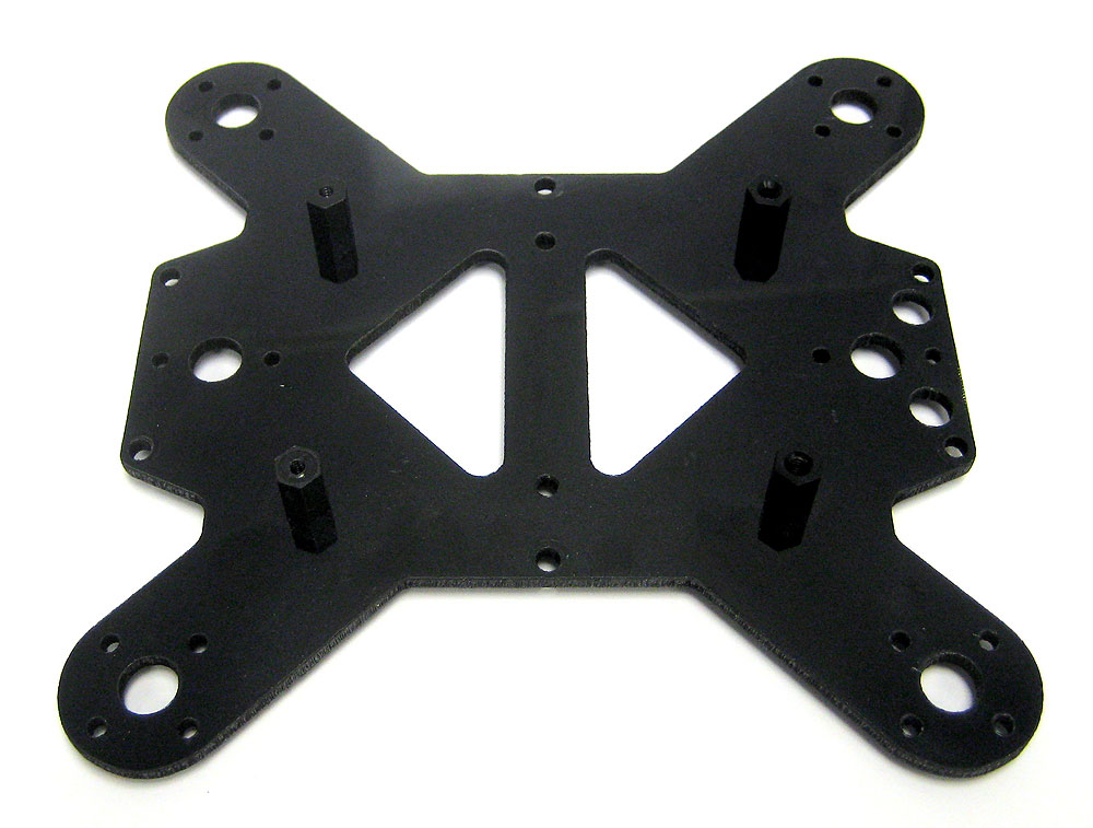 Figure 4b (FlowBotics — F/F spacer).
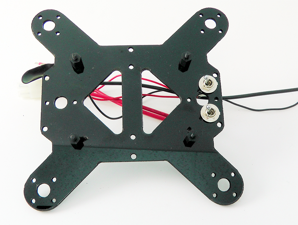 Figure 4c (SSC-32 / BBuino harness routing).
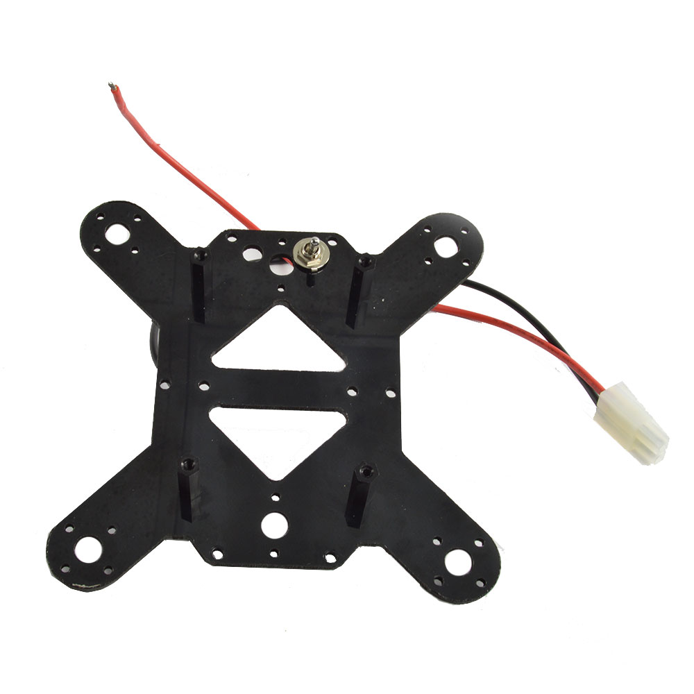 Figure 4d (SSC-32U battery harness).
Attach the legs using right/left legs as indicated. The rear of the robot has circular cutouts for the power connectors. Legs must be at 45° when the servo receives a 1500µs pulse (legs at 90° to each other as shown). Use eight #2 x .250" tapping screws — two per coxa servo.
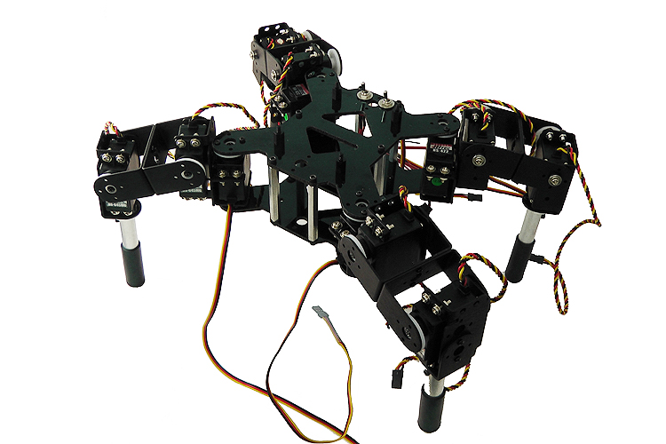 Figure 5.
Option A — BotBoarduino kits: Mount the SSC-32/32U onto the four hex spacers from Step 4a, with the connector facing front. Add four 4-40 x 1" hex spacers on the underside of the top plate to support the BotBoarduino. If using the optional PS2 expansion plate, use the 1" M/F standoffs from that kit.
Option B — FlowBotics kits: Mount the SSC-32/32U onto the four hex spacers from Step 4b. Add four 4-40 x 1/4" screws to secure.
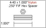
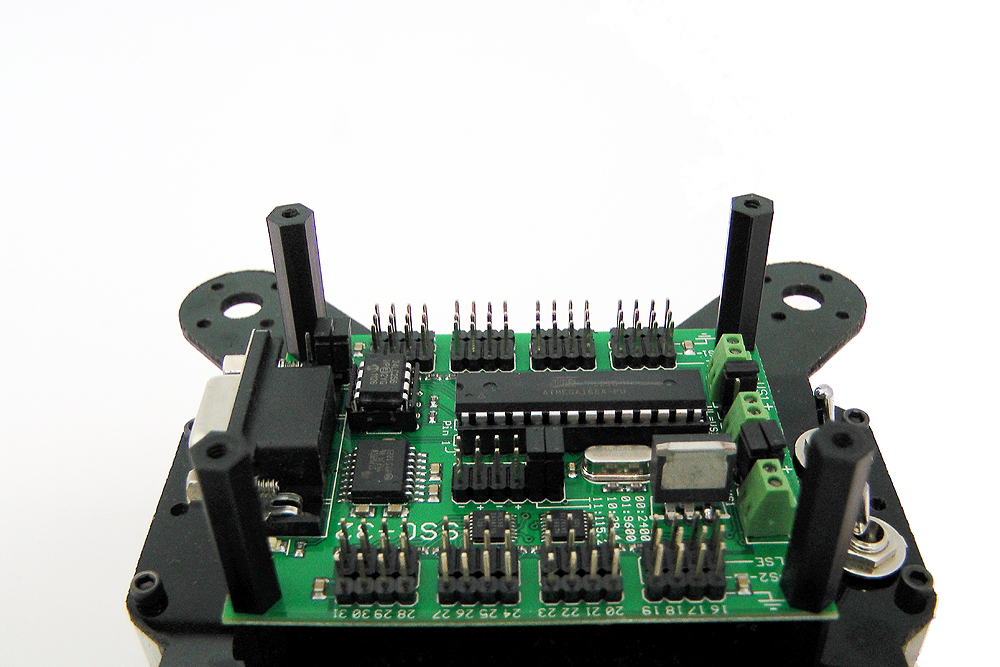 Figure 6a (BotBoarduino kits).
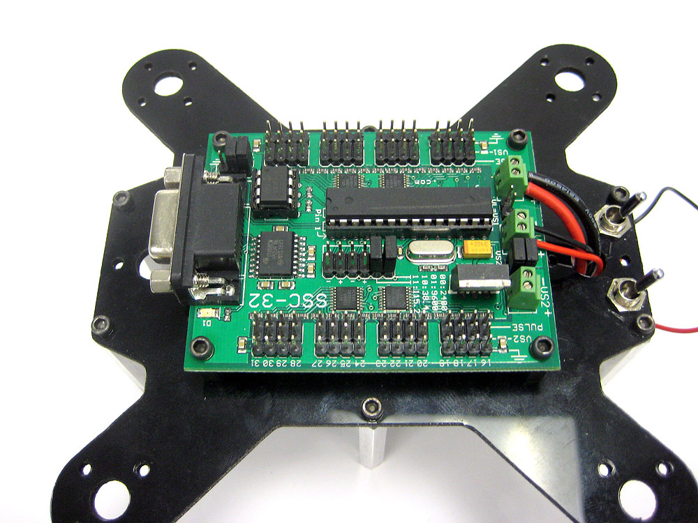 Figure 6b (SSC-32 or SSC-32U alone).
Use a ~2mm flat blade screwdriver on the screw terminals — rotate until the terminal opens completely. Twist wires by hand before inserting. Ensure NO stray wires touch between terminals — a short can discharge the battery rapidly, causing heat or fire.
DOUBLE CHECK: red wire → (+), black wire → (−). Reversed polarity will damage servos and the board.
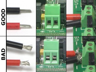 Figure 6 (top = open terminal, bottom = closed).
Connect power and control wiring per your kit configuration. DOUBLE CHECK: red → (+), black → (−).
7a — BotBoarduino + SSC-32 + PS2: Attach power cables per Figure 7a. Wire servos to SSC-32 (Steps 8–9), then connect the SSC-32's VL terminal to the BotBoarduino's VL terminal. Wire with BotBoarduino loose; attach to spacers in Step 12.
7b — BotBoarduino + SSC-32U + PS2: Install SSC-32U on standoffs. Set Baud jumper to 9600. Change the jumper behind the screw terminals to EXT (not USB). Remove the VL=VS jumper.
7c — SSC-32 + Bluetooth (FlowBotics): Install SSC-32 using four 1/4" 4-40 hex screws. Connect XBee breakout board positive pin to C(+) and negative to D(−). Remove Baud jumper to set 9600. Mount power switches at rear.
7d — SSC-32U + Bluetooth (FlowBotics): Same as 7c but using SSC-32U. Mount power switches at rear.
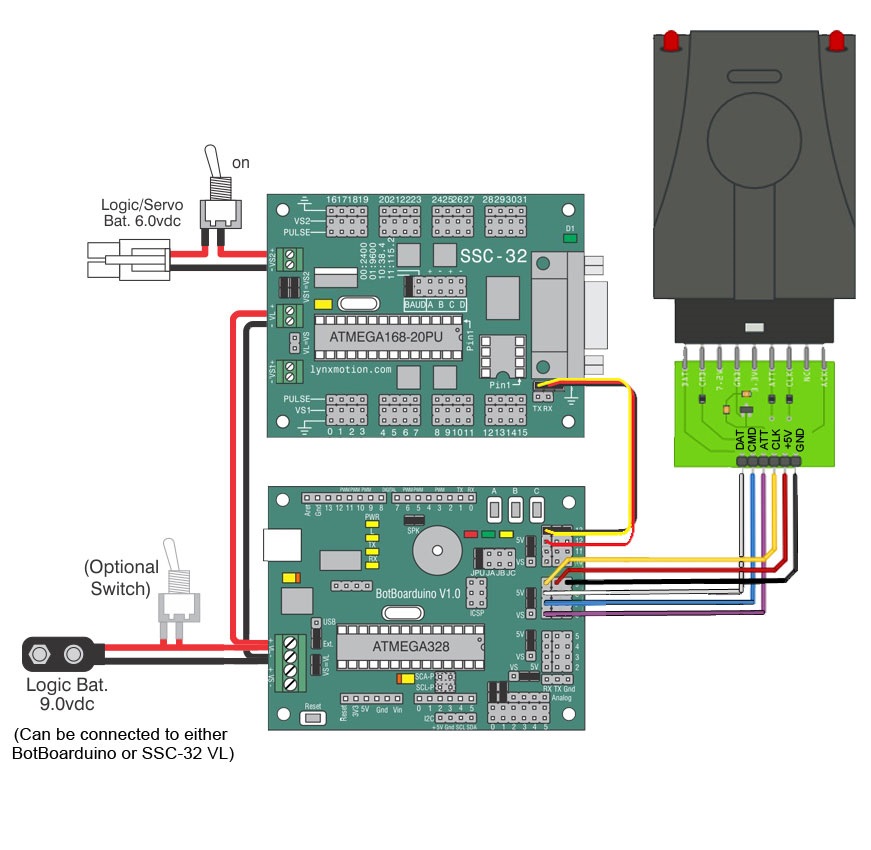
Figure 7a — BotBoarduino + SSC-32 + PS2 v2.
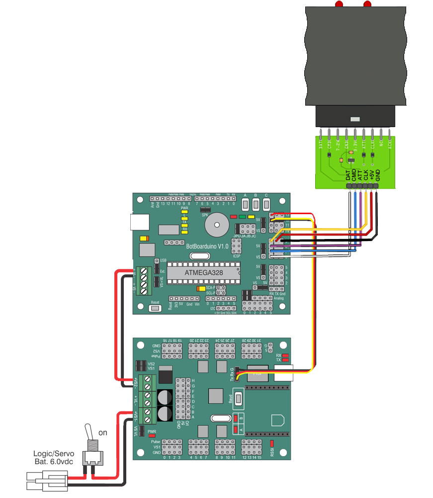
Figure 7b — BotBoarduino + SSC-32U + PS2 v3.
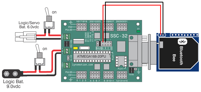
Figure 7c — SSC-32 + Bluetooth.
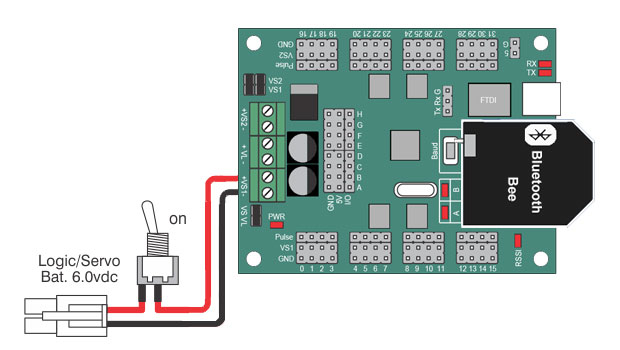
Figure 7d — SSC-32U + Bluetooth.
Plug each servo into the SSC-32 with the yellow signal wire toward the inside (centre) of the board and the black wire toward the outside edge. Cable routing can be tidied in a later step.
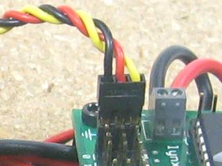 Figure 8 — Servo connector orientation.
Double-check all connections against Figure 9. Confirm red → (+) and black → (−) throughout. Verify jumpers match the configuration above — VL=VS jumper removed; Tx and Rx jumpers removed. BotBoarduino users: the Tx/Rx wiring from SSC-32 to BotBoarduino is not straight-through — the center/power pin must be removed and connected to pin 12 on the BotBoarduino.
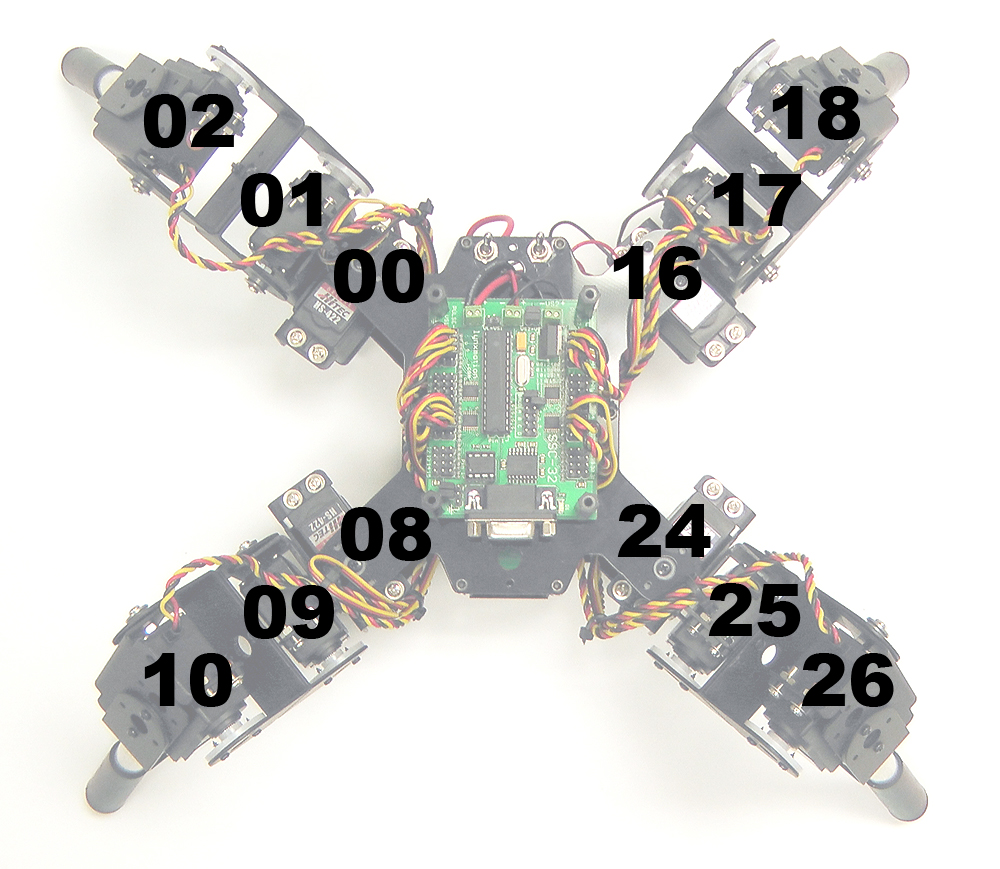
Figure 9 — Servo wiring to SSC-32 / SSC-32U.
SSC-32 / BotBoarduino: Connect a fresh 9V battery and turn the logic switch On — the green LED on the SSC-32 and the power LED on the BotBoarduino should light.
SSC-32U alone: Turn the switch On to power and test the board.
If LEDs do NOT illuminate, immediately power off and double-check all connections. Then turn the switch off.
Connect the 6V battery pack to the battery harness and flip the servo power switch On (logic switch must be Off).
The LEDs should NOT turn on when only servo power is active. If they do, immediately power off and re-check connections.
SSC-32U only: After confirming LEDs stay off with servo power on, turn servo power off, then turn logic power (9V) on — LEDs should illuminate and servos should not move.
Note: Battery packs are not shipped pre-charged. Charge the battery before proceeding.
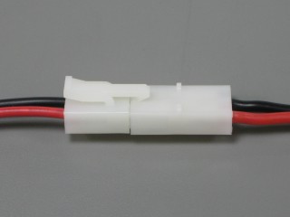 Figure 11 — Battery connection.
Use four 4-40 x 1/4" hex socket screws to mount the BotBoarduino onto the hex spacers on top of the SSC-32, in the orientation shown. If you have the optional PS2 mounting plate, follow those guidelines. Wiring is not shown in Figure 12 for clarity.
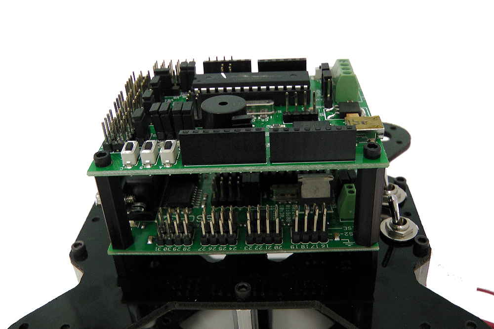 Figure 12 (wires removed for clarity).
SSC-32 (LynxTerm method): Download and install LynxTerm. Disconnect SSC-32 from BotBoarduino and reinstall Tx/Rx jumpers and both Baud jumpers (115200). Power the SSC-32, open LynxTerm, click "All=1500". Click "Reg." → "Read", adjust each servo offset slider to exact 90°, then click "Write" to save to firmware.
SSC-32U (Sequencer Utility method): Download the SSC-32 Servo Sequencer Utility. Connect via USB or Bluetooth. Activate all servos per Figure 9. Click "Configure" and drag each servo knob to exactly 90°. Click "Calibrate" to save offsets to the board. Calibration can also be done via FlowBotics Studio, though it saves locally on the PC rather than to the board.
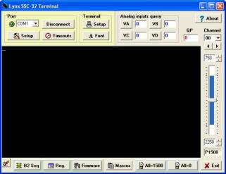 Figure 13a — LynxTerm (SSC-32).
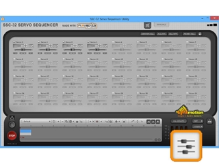 Figure 13b — Sequencer Utility (SSC-32U).
Route all cables cleanly through the body and brackets. Leave enough length at each joint for full range of motion — cables must not get pinched by brackets or servos. Use the cable ties included in the kit; electrical tape or wire wrap also works well.
Ensure the main 6V battery is perfectly centred inside the body so the robot walks properly.
Figure 14 (optional PS2 receiver and mount shown).
BotBoarduino kits: Sample PS2 control code is available on GitHub. For help with the Arduino library, refer to www.arduino.cc.
FlowBotics Studio kits: Install FlowBotics Studio and open the included quadruped project.