
BotBoarduino Manual
| Table of Contents | Links |
BotBoarduino Hardware Information.
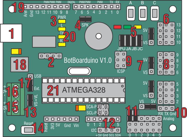
The image above illustrates the shorting bar jumpers (the black rectangles) as they are on the board as it is shipped. The jumpers are used to set operating parameters for the board. It should not be assumed that they are correct for your project as changes are likely to be required. Please consult the tutorial for your project for the proper shorting bar jumper positions.
The BotBoarduino is 3.00" x 2.30" with 0.125" holes set in 0.15" from each edge.
- The BotBoarduino is based on the Arduino Duemilanove. In the Arduino programming environment you must select "Arduino Duemilanove w/ ATmega328". Simply plug a USB Mini cable from this plug to a free USB port on your PC for programming the processor and receiving debug information. For help with USB drivers, go to the official Arduino page. To prevent damaging the board's USB port, you must remove the USB cable from a MOBILE robot!
- These four pins are connected to the FTDI's CTS, DSR, DCD, and RI signals. You should never have to worry about these pins. Use them only if you know what you're doing as these pins can prevent the BotBoarduino from being programmed.
- This is a Power Good LED. When you have successfully applied power to the onboard regulator, the yellow LED will turn on.
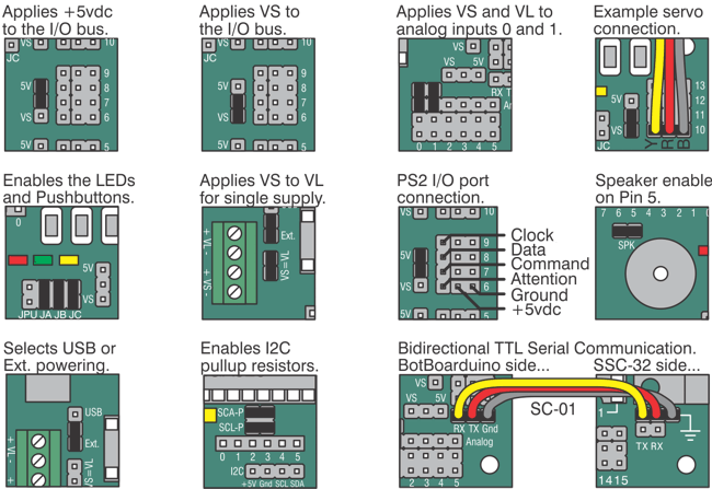
- This shorting bar enables the onboard speaker. To use the speaker, send the appropriate sound generating command to Pin 5. Note, the I/O pin drives a transistor amplifier. It does not drive the speaker directly.
- The 3 LEDs and Pushbuttons use only 3 I/O lines to make a simple user interface for your program. By making the I/O line a low output the LED
can be turned on. By briefly making the I/O line an input the I/O line can be read to see if a button is being pressed. However,
do NOT make the I/O line a high output and press a button, as damage to the I/O pin can occur. The shorting bars
directly above JA, JB, and JC will need to be
installed for these LEDs and Pushbuttons to be used.
Chip I/O PB/LED Pin 7 A Red Pin 8 B Green Pin 9 C Yellow - This is where you connect servos, motor controllers, sensors, etc. to the microcontroller. Use caution when connecting anything the the I/O bus. Never connect anything while the power is on. The outside row is ground, the middle row is power, and the inside row are the IO pins.
- This is where you configure the I/O bus center row to use VL (+5vdc from the onboard regulator) or VS (direct from the Servo Power Input). This is done in banks of four I/O pins. Caution, applying the servo voltage to this row with a 5vdc peripheral installed will cause damage to the peripheral.
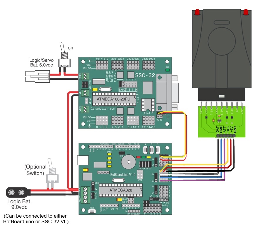
- This port is for connecting a Sony Playstation controller to use as a robot controller.
The Lynxmotion, Sony, and Madcatz controllers we tested only required a 1K pullup on Pin 6,
which is built into the board and must be enabled by installing a jumper on the JPU. Other
brands may require a pullup on Pin 9, which is not included. Note, some controllers require the green wire
to be connected to 7.5vdc to enable vibrating motors, or wireless operation. The Playstation 2 cables' coloring differs from different
production runs. Please refer to the table in the Shorting Bars and Connections section to verify the color coding and
connections for your cable.
Pin PS2 Function Pin 8 DAT Pin 7 CMD Pin 6 ATT Pin 9 CLK - This pin group breaks out the ICSP pins. These allow you to burn a bootloader onto the Atmega328 or program the chip with an external programmer. Do not connect anything to these pins unless you know what you are doing.
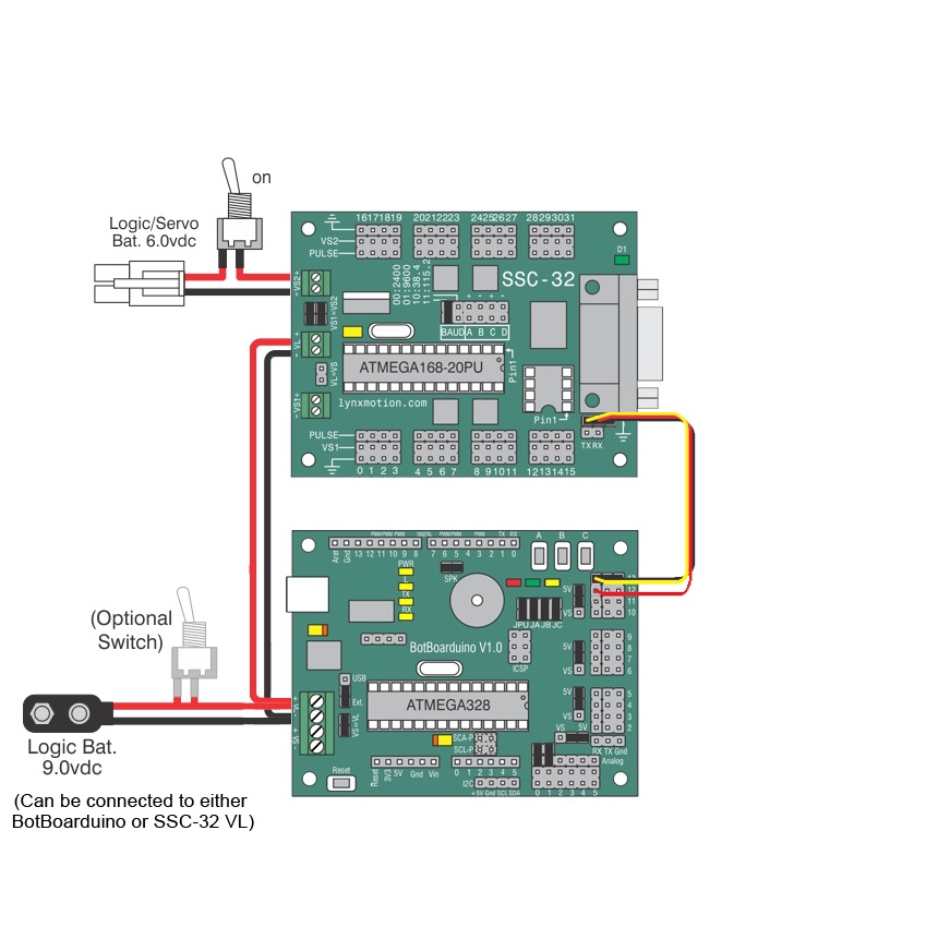
- This connecter brings out pins 0 and 1 of the arduino along with ground in such a way that you can connect the BotBoarduino to an SSC-32 with any servo extension cable. You will need to remove anything connected to these pins while programming.
- This allows the VL and/or VS inputs to be connected to two of the AtMega328's analog inputs through a 4:1 voltage divider. For example, if the
battery voltage were 9vdc, the analog input would see 2.25vdc.
Chip I/O Use A0 V-Servo / General Purpose A1 V-Logic / General Purpose A2 - A5 General Purpose - These headers bring out analog pins A4 and A5 for use with the I2C comunication protocol. To use this header you must install jumpers horizontally across the SDA-P and SCL-P headers.
- This allows you to power the Servos and Logic from the same battery. It simply connects the VS input to the VL input. Caution, when using this option do NOT use the VL input.
- This button will reset the micro when pressed. This can be useful for starting different programs depending on which SUI button is pressed on reset.
- This is the VS (servo voltage) input. Servo voltage can be 4.8vdc to 7.2vdc. However, some micro servos will not tolerate more than 6vdc. This
input is used to provide power for the servos only, or to provide power to both VL and VS using the VS=VL jumper. See Item 13.
Board Input VS + RED VS - BLACK - This is the VL (logic voltage) input. This input is normally used with a 9vdc battery connector to provide power to the microcontroller and
anything connected to the 5vdc lines on the board. This input can be used to isolate the VL from the VS (servo voltage).
Board Input VL + RED VL - BLACK - This header selects the Logic Power source for the board. Select USB to power the Logic from the onboard USB port or Select EXT to power the board from the VL terminal.
- The Low Dropout regulator will provide 5vdc out with as little as 5.4vdc coming in. This is important when operating your robot from a battery. It can accept a maximum of 12vdc in. The regulator is rated for 1.5A.
- These headers are spaced to accept all Arduino compatible Shields and Extensions.
- Status LEDs.
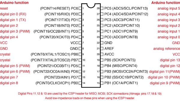
LED Function L Directly connected to P13 on the Arduino chip TX Blinks when sending data RX Blinks when receiving data - This is where the Atmega 328 chip is plugged in. Atmega328 pin map:
Shorting Bar Jumpers and Connectors at a glance.
The Playstation 2 cables' coloring differs from different production runs. Please refer to the diagram below to verify the color coding on your cable.
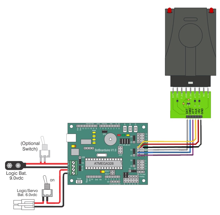
The yellow power (PWR) LED should glow if the regulator is getting the proper power. You must make sure to connect the battery or wall pack with the proper polarity. This means the red wire is positive (+) and the black wire is ground (-). If you connect the battery or wall pack with the polarity reversed, the regulator and the microcontroller can be instantaneously and permanently damaged! Check your wiring carefully before applying power.
If SSC-32 is connected to RX/TX/Gnd (hardware serial port on pin 0 and 1) it must be removed while programming! This is because the USB port shares the same IO pins.
The maximum voltage for VL is 12vdc. If you use a higher voltage the regulator may overheat and you could get burned!
Confirm that the Atmega 328 chip's notch is aligned with the socket's notch.
In the Arduino programming environment, make sure you have selected "Arduino Duemilanove w/ ATmega328".
The Lynxmotion PS2 controller has issues with the analog mode on the Lynxmotoin left pad (often displaying 0 rather than analog values). We suggest using the joysticks as alternative analog inputs.