
RC Servo Mid Position Tutorial
| Servo Mid Position Tutorial.
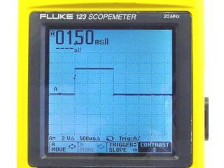
03/25/2008. By James Frye. Building Lynxmotion kits requires adjusting the servo to its mid position (center of rotation). In order to move the servo's output shaft to its mid position, the servo needs to receive 1.5mS, positive-going pulses every 20mS. This tutorial will cover creating the necessary pulses from off-the-shelf controllers. |
 Too cool! |
| Connecting Power. The first step in getting your SSC-32 or Bot Board ready to control servos is to provide voltage. This is accomplished using either our BATC-01 battery cable or our WH-01 battery cable with switch. If your cable has tinned ends, cut off the tinned part and strip the plastic cover off about 1/4" from the new end. The reason for doing this is the screw terminals can't properly tighten down on a tinned wire. Remember, the red wire is (+) and the black wire is (-). For now, make sure the VS=VL jumper is installed, but you may be instructed to remove it later. Attach a charged 6.0-7.2vdc battery to the connector and turn on the switch. The green LED should light on the board if all is well. If not, quickly remove the battery pack and double check your work! |
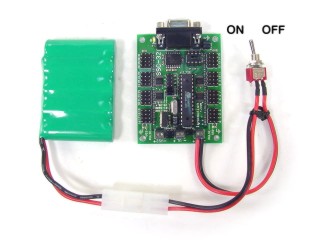 With Battery. |
| SSC-32. To allow custom servo positioning on powerup, the servo controller does not automatically generate pulses. Apply 6-7.2vdc to the VS1 terminal and install the following jumpers: VS=VL, VS1=VS2, Both baud for 115.2k, TX and RX to enable DB9 port. Connect a DB9 cable from the board to a free serial port. You can download and run Lynx SSC-32 Terminal. Change the port to your Com port. Click on "All = 1500". Plug a servo into any port with the black wire closest to the outside of the board. The servo controller will generate these pulses until powered down. Another way is the software method: #0 P1500 <cr>. This will generate pulses on the channel following the "#" only. More information is available in the SSC-32 manual. If you are using RIOS-01 or SEQ-01, both programs have this function built in. Consult the users manual for more information. |
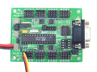 SSC-32. |
| |
|
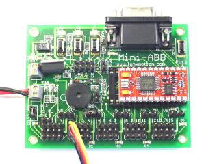
| Bot Board / BASIC Atom. Apply 6-7.2vdc to the VS connector and install the VS=VL jumper. Also install the VS jumper for the first four I/O pins. Program the Atom with the following code to generate the pulses on I/O Pin 0. Plug the servo into I/O Pin 0 with the black wire closest to the outside of the board.
|
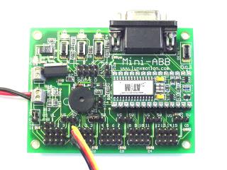 BASIC Atom. |
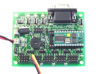
| Bot Board / BASIC Atom Pro. Apply 6-7.2vdc to the VS connector and install the VS=VL jumper. Also install the VS jumper for the first four I/O pins. Program the Atom with the following code to generate the pulses on I/O Pin 0. Plug the servo into I/O Pin 0 with the black wire closest to the outside of the board. IDE v8.0.1.3+ |
 BASIC Atom Pro. |
| Bot Board / BASIC Stamp 2 / BS2-E. Apply 6-7.2vdc to the VS connector and install the VS=VL jumper. Also install the VS jumper for the first four I/O pins. Program the BS2 with the following code to generate the pulses on I/O Pin 0. Plug the servo into I/O Pin 0 with the black wire closest to the outside of the board.
|
 BASIC Stamp. |
| SSC-12. Apply 6-7.2vdc to the red and black wires. If powered correctly, the green LED will illuminate. The pulses are automatically generated. Plug a servo into any port with the black wire closest to the outside of the board. |
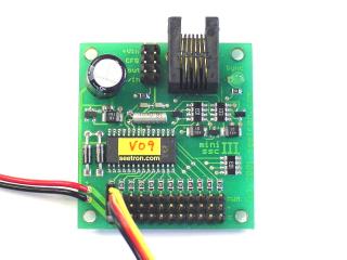 SSC-12. |
| Mini SSC-II. Connect a 9vdc battery to the SSC power input and apply 4.8-7.2vdc to the SVO power input. If powered correctly, the green LED will illuminate. The pulses are automatically generated. Plug a servo into any port with the black wire closest to the outside of the board. |
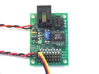 Mini SSC-II. |