
LSS-PRO Configuration Software
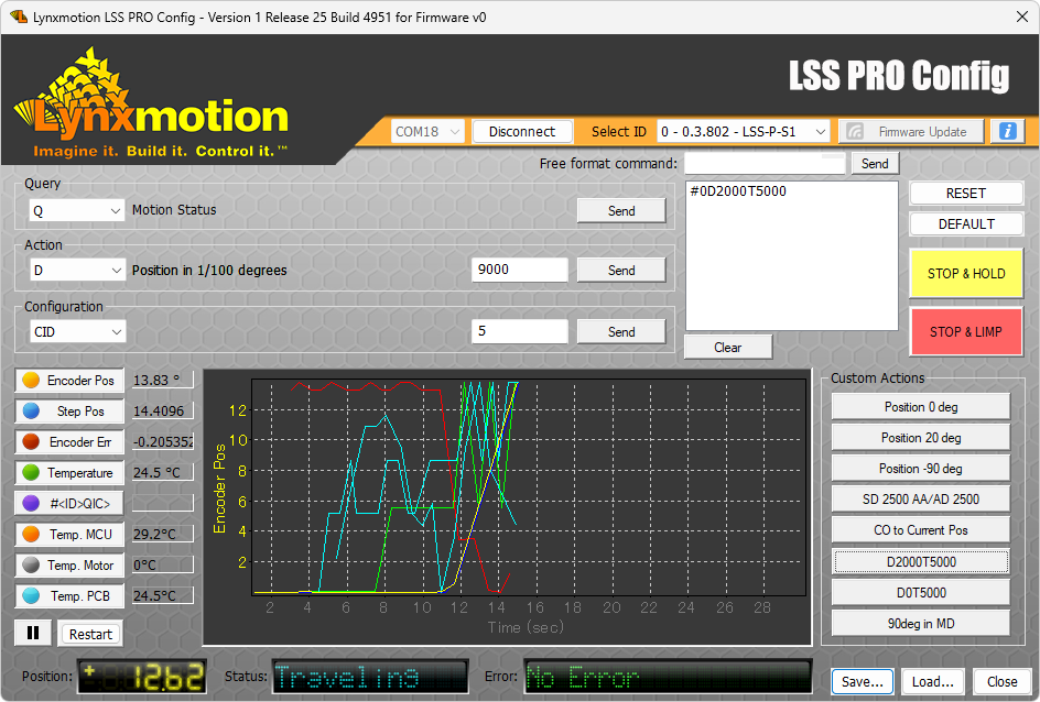

Table of Contents
Description
The Lynxmotion Smart Servo PRO Configuration Software (“LSS PRO Config” for short) is intended to be a tool to quickly interact with the Lynxmotion Professional Smart Servos (LSS-P) loaded with proprietary Lynxmotion firmware. Features include sending action and configuration commands, queries (and receiving the reply), updating the firmware, monitoring sensor data and more. The software works on Windows 7 operating systems and above. The software is intended as a quick starting point to better understand the servo before developing custom applications using the human-readable communication protocol.
Note: The software can be connected to multiple servos, but the interface can only control and communicate with one at any time (unless using the free format commands described below). Each servo must have a unique ID. The servo(s) must be powered correctly and connected to the computer via USB from the first servo in the BUS.
Features
- Send action, configuration and query commands to an individual PRO servo
- Obtain visual feedback from various onboard sensors
- Create custom actions for testing purpose
- Update PRO servo’s firmware
- Auto-Update if connected to Internet
User Guide
This section provides step-by-step instructions and tips to help you get the most out of your LSS-P actuator. Whether you are setting up your hardware, configuring your servos, or troubleshooting, you'll find detailed information to assist you. Follow the guidelines below to ensure optimal performance and a smooth experience.
Information

- The Information (capital I) button at the top right of the interface leads to this user guide.
Connection
In order for the LSS PRO Config software to detect the servos, the correct USB to serial drivers must be installed on the computer, and the servo must be powered. Windows will automatically detect and install the drivers.

- Select the appropriate COM port
- Click on the "Connect" button (All servos in the communication BUS should be detected)
- Select a particular servo from the list
Note: The interface will then display and control that single actuator.
Safety & Useful Buttons
This section includes the important emergency stop (removes power from the motors via software) and other useful commands.
Note: Those commands are sent to the selected servo, if "254 - All servos" is selected then it will be sent to all of them.
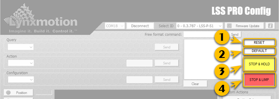
- This button sends a RESET command. More information HERE
- This resets the servo to factory default settings, removing all configurations, including the ID. More information HERE
- This command stops the actuator at whatever angle it is (whether during a motion or already at an angle) and causes it to hold that position (motor is powered and holding). The following command is sent to all servos, not just the one connected via USB.
Command sent: #254H<cr>
This command stops the actuator at whatever angle it is (whether during a motion or already at an angle) and causes it to hold that position (motor is powered and holding). The following command is sent to all servos, not just the one connected via USB.
Command sent: #254L<cr>
Just like the emergency stop button on the 36V large power supply (provided with each PRO arm), the E-Stop is meant to be used in emergency only since power is cut to all motors, which may result in joints rotating because of high counter-torque or forces being applied. In the case of a robotic arm, the arm may fall and damage itself or whatever is in its environment.
Status
As a servo is intended to be moved to specific angles, the position of the servo, this section provides relevant angular and motion information to the user on what's happening with their actuator.
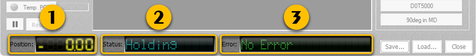
- The position section shows the current angle of the output shaft of the servo in relation to its configured angular origin (0 degrees, including any adjustments using the Origin Offset command). It also displays angles to 0.01 degrees of accuracy, as well as below 0 degrees and over 360 degrees. It’s important to note any angle beyond 0 to 360 is a calculated, or "virtual" position as the internal sensor can only read 0 to 360 degrees. The multi-turn angle is retained even after a power cycle.
- Status of what the actuator is currently doing. More information HERE
- Error encountered. More information HERE
Note: Most errors will require that the cause of the problem to be solved before proceeding. The servo should either be Reset or set Limp. To view and resolve any errors, go to the troubleshooting section
Servo Control
In order to view the various commands available for each drop-down, a PRO servo needs to be properly connected to the computer, powered, turned on and detected.
Query
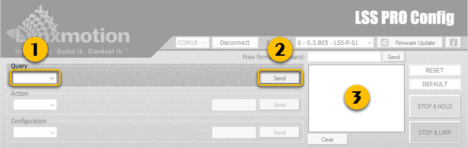
- The drop down list below Query provides a list of most query commands possible. More information click HERE
- Click the "Send" button to initiate the Query.
- The Query protocol command will be displayed here as well as the answer from the actuator. (ex: #1QID / *1QID1)
Action
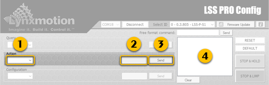
- The drop down list below Action provides a list of most action commands possible. More information click HERE.
- Input the value of the Action required in the text input field. (ex: 9000 for a 90deg move)
- Click the "Send" button to initiate the Action.
- The Action protocol command will be displayed here and the actuator should be doing it.
Configuration
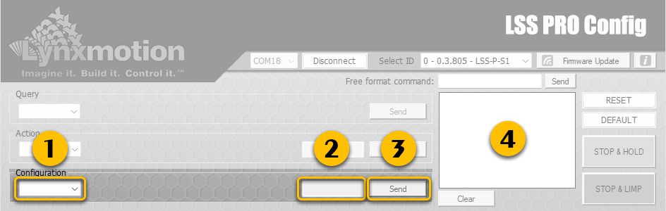
- The drop down list below Configuration provides a list of most configuration commands possible. More information click HERE.
- Input the value of the Configuration required in the text input field. (ex: 1 for an ID change to 1)
- Click the "Send" button to initiate the Configuration.
- The Configuration protocol command will be displayed here.
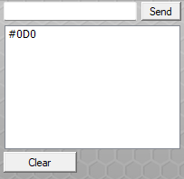
Free format command
This command line interface allows the user to send commands, including those not otherwise found in the drop-down list, as well as any special commands provided by Lynxmotion staff. Once sent the commands will be displayed in the area bellow (like a terminal) and can be cleared if required. This can help with debugging or better understanding the communication protocol.
Telemetry
A graph within the software is used to display output of any query commands, which can include sensor data or calculated data.
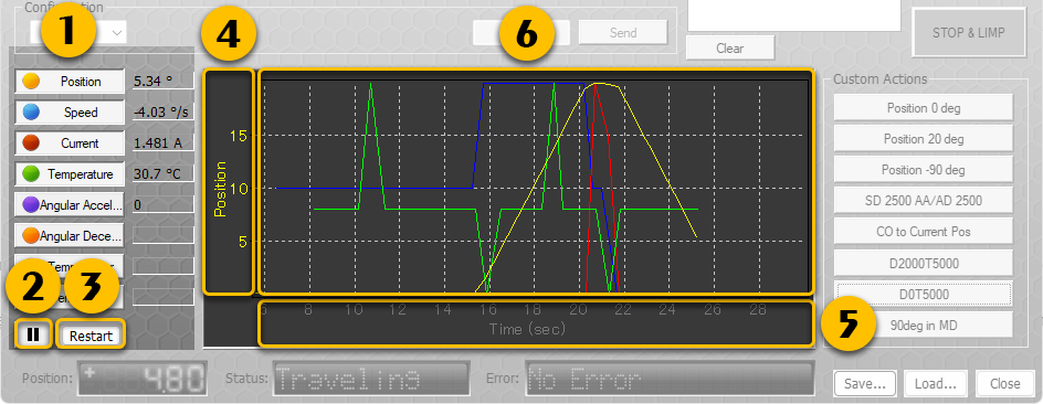
- To activate a specific value, click on the button once, and click again if you'd like to disable it. The software starts recording and displaying the data as soon as one query is activated.
- Pressing Pause will stop recording until clicked again to resume.
- Pressing Restart will wipe all the recorded values and start fresh.
- The Y-axis of the graph auto-scales depending on what output is selected. To switch between traces, use the mouse wheel and confirm that the y axis label is the one you want.
- The X-axis displays the time & expands up to 20 minutes then scrolls a 20 minute time window.
- Saving the data is possible by right clicking on the graph and selecting Copy. It's then possible to paste the data in a spreadsheet application (Excel / Google Sheets).
Personalized Query
To change the query for a specific button, "CTRL + CLICK" on the desired button and the following popup interface will be displayed:
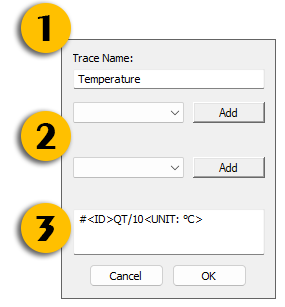
- Trace Name: Displayed name for that particular query.
- Two separate "Add" buttons with corresponding drop down menus are present which are shortcuts to add to the query in (3)
- The specific Query that will be sent to the actuator plus displayed units for the interface.
Custom Actions
This list of assignable buttons allows the user to select specific commands to send to the servo. These can be used to quickly position the servo to specific angles, experiment with different speeds and more.
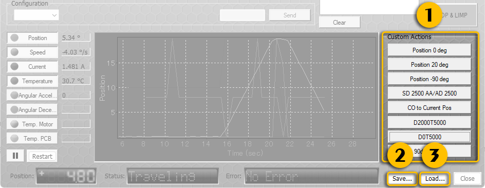
- All of those buttons can be set to trigger any action required.
- Save will let you do a backup of the current Custom Actions.
- Load will let you select and load a previously saved Custom Action file.
Personalized Action
To change the Action for a specific button, "CTRL + CLICK" on the desired button, and this interface will then be displayed:
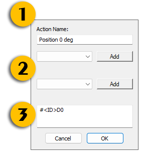
- Action Name: Displayed name for that particular action.
- Two separate "Add" button and corresponding drop down menus which are shortcuts to add to the action in (3)
- Action command that will be sent to the actuator plus displayed units for the interface.
Firmware Update
It is good to periodically check for firmware updates for the servos. A firmware update requires that the computer running the software be connected to the Internet.
Firmware updates can resolve bugs or add improvements. The information in this Wiki (for example the PRO Communication Protocol Page) will always refer to the latest version of firmware (though in certain instances will detail which firmware version of the firmware the feature or function started with).

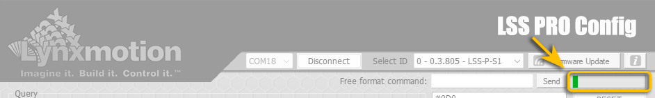
When a firmware update is available, the logo will turn green, as shown in the image above..
Note: Only a servo connected via USB can be updated and all the other servos on the bus will not be displayed with a green logo unless connected directly via USB.
Online Update
- Select the servo ID to see if a firmware update is available for that servo
- If the logo is green, click on the "Firmware Update" button
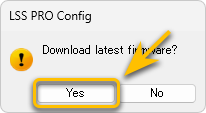
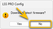
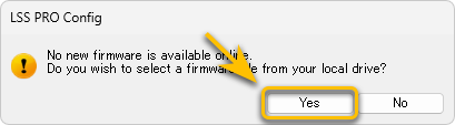
- A message will ask you if you want do download the latest firmware, click Yes.
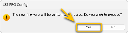
- The time to download the update should be fast, and once downloaded another message will ask you if you want to proceed; click Yes.
- The servo will be put in "Firmware Update" mode and the LED on the servo will start flashing. A progress bar will show the progress. DO NOT UNPLUG or REMOVE POWER from the servo while updating.
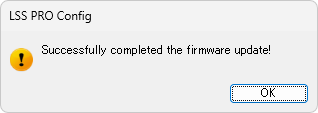
- Once the procedure is done you will have a confirmation pop-up.
Offline Update
In rare occasions, our staff could ask you to upload a firmware which they provided. A link to this procedure will also be provided.
- Select the servo ID that requires a firmware update
- Click on the "Firmware Update" button and depending on the pop-up select as shown.
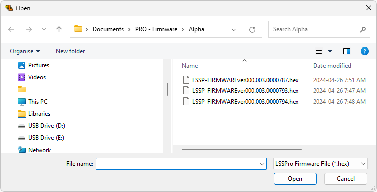
- Browse to and select & open the firmware file provided by our staff (saved locally on your computer).
- Another message will ask you if you want to proceed; click Yes.
- The servo will be put in "Firmware Update" mode and the LED on the servo will start flashing. A progress bar will show the progress. DO NOT UNPLUG or REMOVE POWER from the servo while updating.
- Once the procedure is done you will have a confirmation pop-up.
Troubleshooting
Connection Error
LSS PRO device not found at this port!
If the software does not detect any servos, this can be for multiple reasons:
- Forgot to connect the USB port to ONLY the first servo of the assembly
- Servo not connected to the power supply, or power supply not turned on.
- Wrong COM port selected in the software
- USB drivers have not been properly installed
- Advanced users may have written their own firmware (Arduino format) and uploaded it to the microcontroller within the servo. The PRO Config software cannot be used in this instance.
To resolve this issue:
- Ensure the power is ON.
- If you have the 30V power supply, ensure the switch is set to ON
- If you have the 36V power supply, also ensure the switch is set to ON & E-Stop button is not pressed
- Verify the Device Manager in Windows to see if the COM port is present
Software Issues
Firmware update stalled / frozen
If the LSS Config screen freezes during a firmware update or the process takes many minutes without an update.
To resolve this issue:
- Power cycle the servo, keeping it connected via USB to the computer.
- Restart the LSS PRO Config application
- The update should resume.
If the firmware was being updated using a local file (rare), then the Firmware Update button needs to be pressed again for the update process to restart.
Interface freezes
If the interface freezes for any reason outside of a Firmware update, end the Windows Task corresponding to the LSS Config via Windows’ Task Manager (accessible via shortcut by simultaneously pressing CTRL + SHIFT + ESC on the keyboard).
Wrong Servo Detected
If the display is showing the wrong servo detected (for example if you have a STANDARD servo connected, but it’s appearing as a MEGA), which should not happen, please reach out to RobotShop with details and instructions will be provided on how to correct this.
Appearance
If the appearance or aesthetics seem “off”, this may be due to the "Scale" factor in Windows 11, set it to 100%.