550mm 5DoF Initial Setup
1.0 - Firmware | |
Before proceeding, verify that each servo is running the latest firmware and update if necessary. See LSS Config software page for details on how to update firmware per servo. Important: At this time, firmware updates need to be done per servo (not the arm as a whole), with each servo connected directly to the computer via USB for their own update. | |
LSS-PRO Firmware Update | |
Periodically check for firmware updates for the servos by connecting the arm to the LSS Config, selecting each servo and seeing if a firmware update is available. Note that a firmware update requires that the computer running the PRO Config software is connected to the Internet. Firmware updates can resolve bugs or add improvements. The information in this Wiki (for example the PRO Communication Protocol Page) will always refer to the latest version of firmware (though in certain instances will detail which firmware version of the firmware the feature or function started with).
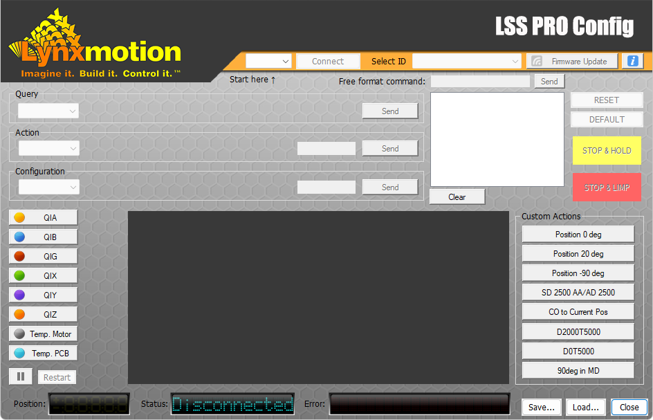
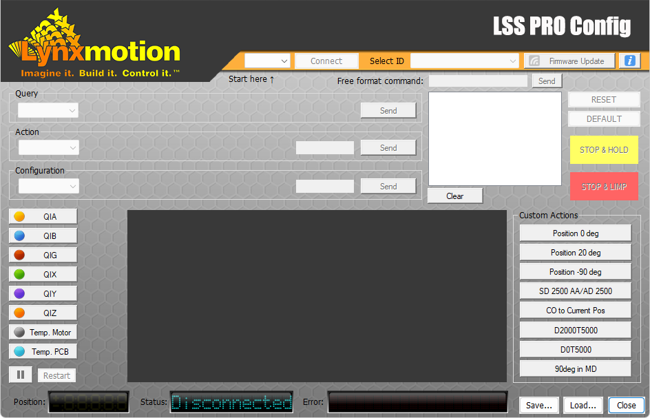
When a firmware update is available, the logo will turn green, as shown in the image above.. Note: Only a servo connected via USB can be updated and all the other servos on the bus will not be displayed with a green logo unless connected directly via USB. Note: Unless specified otherwise, existing configurations are retained after firmware updates | |
Online Update | |
| 1. Select the servo ID next to "Select ID" to see if a firmware update is available for that servo | |
| 2. If the logo is green, click on the "Firmware Update" button | |
3. A message will ask you if you want do download the latest firmware, click Yes.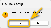 | |
4. The time to download the update should be fast, and once downloaded another message will ask you if you want to proceed; click Yes. | |
5. The servo will be put in "Firmware Update" mode and the LED on the servo will start flashing. A progress bar will show the progress of the update. DO NOT UNPLUG or REMOVE POWER from the servo while updating. | |
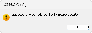
| 6. Once the update is finished the software will display a confirmation pop-up. | |
 | |
Offline Update | |
In rare occasions, our staff could ask you to upload a firmware which they provided. A link to this procedure will also be provided. | |
| 1. Select the servo ID that requires a firmware update | |
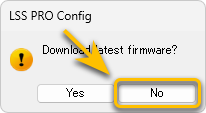
2. Click on the "Firmware Update" button and depending on the pop-up select as shown.
| |
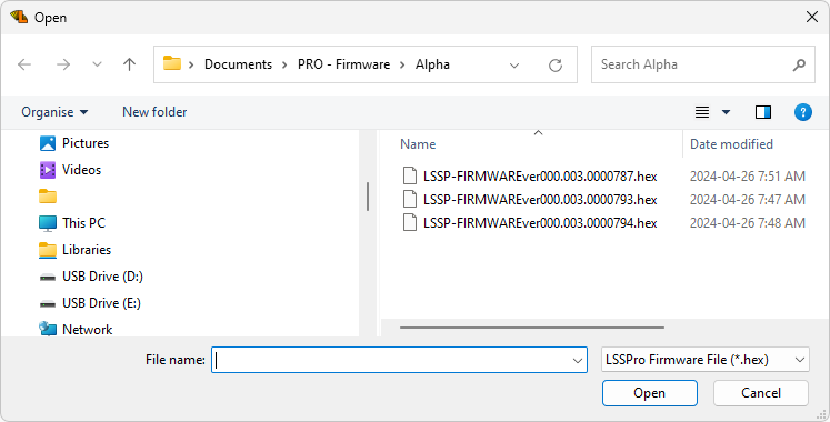
3. Browse to, select & open the firmware file provided by our staff (saved locally on your computer). | |
4. Another message will ask you if you want to proceed; click Yes. | |
5. The servo will be put in "Firmware Update" mode and the LED on the servo will start flashing. A progress bar will show the progress. DO NOT UNPLUG or REMOVE POWER from the servo while updating. | |
6. Once the procedure is done you will have a confirmation pop-up. | |
2.0 - Actuator ID | |
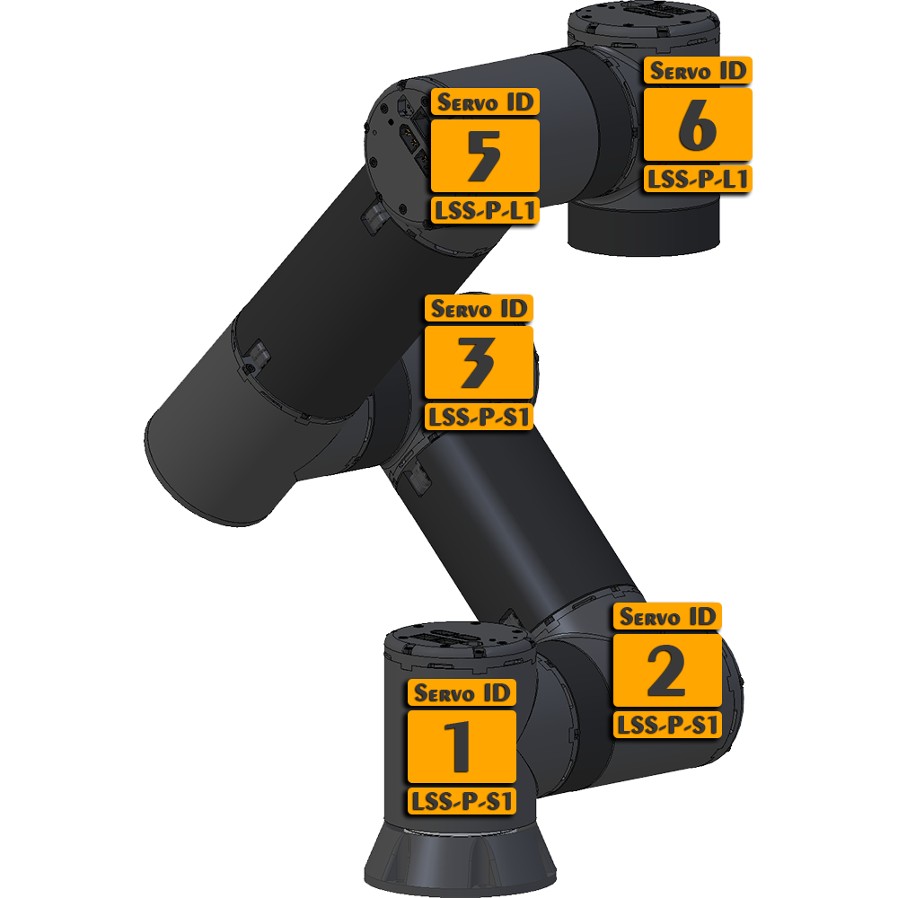
It's always best to verify the firmware version and update to the latest before doing anything else. J1: LSS-P-S1 / Standard / ID1 | |
 | |
LSS-PRO Configure IDs | |
1. Wiring WARNING:Do not hot plug the servo! Make sure the power supply is turned OFF (and waited at least 10s for it to completely discharge its internal capacitor) before connecting it to the LSS-P actuator
If you are using a battery, ensure there is an On/Off switch between the battery and the servo(s). | |
2. Power ON
| |
3. LSS PRO Config Software
| |
4. Connect to the BUS
| |
5. Actuator Selection
| |
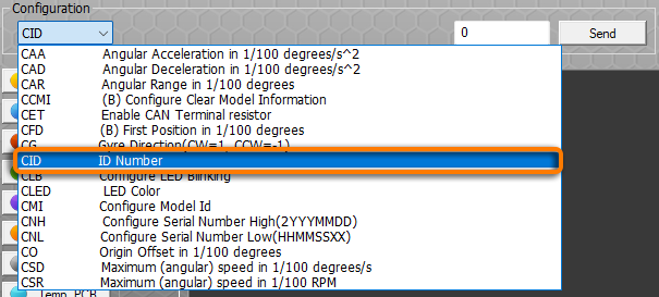
6. Set the servo's ID
| |
7. Confirm
At that point your Actuator should have the new ID configured. | |
| 8. Repeat individualls for each servo in the BUS ensuring only one servo at a time is connected via its own USB to the software. | |
3.0 - CAN bus | |
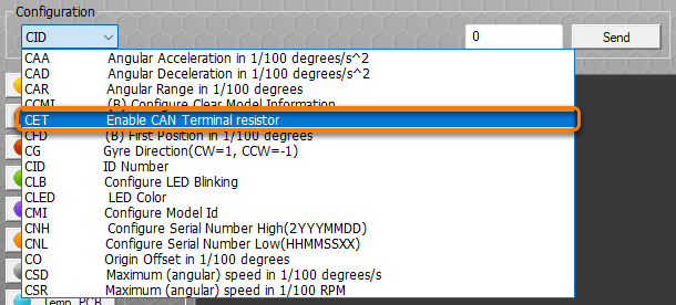
The LSS-P actuators communicate from one another using a CAN bus and to be stable it require an "end of line" resistor to be set. It suppress reflections as well as return the bus to its recessive or idle state By default all actuator have this resistor set to ON and the actuator that are in the middle of the bus need to be deactivated. It's quite easy to do so with a serial command using the LSS PRO Configuration software. More about it here: LSS-PRO Communication Protocol / Enable CAN Terminal Resistor | |
LSS-PRO Configure CAN BusThe LSS PRO servos are meant to be daisy chained in a CAM Bus. The last servo in this BUS needs to be configured as the last servo. A terminal resistor in a CAN bus ensures signal integrity by reducing reflections on the communication line, helping to maintain stable data transmission. There is no need for a physical resistor as this is set via a configuration command. | |
1. Wiring WARNING:Do not hot plug the servo! Make sure the power supply is turned OFF (and waited at least 10s for it to completely discharge its internal capacitor) before connecting it to the LSS-P actuator
If you are using a battery, ensure there is an On/Off switch between the battery and the servo(s). | |
2. Power-Up
| |
3. LSS PRO Config Software
| |
4. Connection
| |
5. Actuator Selection
| |
6. Set the ID
| |


