550mm 6DoF Zero Calibration
- 1.0 - Position the Arm
- 2.0 - Configure Temporary Offsets
- 3.0 - Move to real Zero
- 4.0 - Configure final Offsets
| The Lynxmotion Smart Servo PRO (LSS-P) have multi-turn capabilities which require that an origin (zero) angle be configured for each application. In theory the origin can be anywhere between 0 and 360 degrees, but to ensure the physical arm's angles match the angular commands sent from software, a known "origin" or "zero" angle for each servo must be accurately set. Using the LSS-PRO Configuration Software and positioning the arm to a known, reproduceable position will allow for this, regardless of the "random" angle at which each joint was assembled. This requires a flat surface onto which the assembled arm can be placed. | |
1.0 - Position the Arm | |
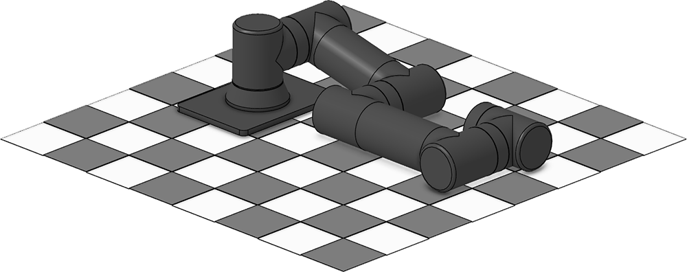
Lay the arm flat on the surface, ensuring that the servos in the elbow and wrist are fully in contact and flat against the surface as shown in the images below. This procedure can be done with or without the base plate connected, but assumes the arm's base is connected to J1. Two joints won't be constrained in this position and therefore cannot be accurately zeroed: Joint 1 (base) / ID1 and gripper (rotation) Joint 6 / ID6. It is left to the user to center these servos as needed using the procedure below. | |
| Side View | |
| Angular View | |
2.0 - Configure Temporary Offsets | |
Using the LSS-PRO Configuration Software, which was already used for the LSS-PRO Configure IDs section, connect to the arm using the first actuator in the base (J1). Note: Joint 1 and 6 can be configured visually as they are not restricted by placing it on the table. Repeat the following steps for each joints | |
2.1 - Select the Joint / ID to configure
| |
2.2 - In the "Custom Actions" press the "CO to Current Pos" shortcut button. This will read the current position and write it to memory as the origin, making it the new Zero degree angle.
| |
2.3 - Click the Yellow "Stop & Hold" button
| |
| 2.4 - Repeat for each Joint / ID | |
3.0 - Move to real Zero | |
Now that the angle of joints 2 to 5 are known and absolute, the arm will be moved a vertical "default" position. For this, only two joints need to be moved: J2 / ID2 and J3 / ID3. As mentioned above, the known angles between J2 and J3 and J3 and J4 will differ if the SES-P Base Adaptation Plate is installed or not so be sure to use the correct angles below for your particular application / mounting. Using the "Free format command:" section of the Configuration Software move the following Joints / ID with the command provided bellow.
| |
3.1 - WITHOUT Base Adaptation Plate
Explanation: The known angle between the shoulder (J2) and vertical 99.98 degrees. The known angle between the elbow (J3) and wrist (J5) is 9.98 degrees from aligning vertically with J2 and J3. | |
3.2 - WITH Base Adaptation Plate
Explanation: The known angle between the shoulder (J2) and vertical 102.58 degrees. The known angle between the elbow (J3) and wrist (J5) is 12.58 degrees from aligning vertically with J2 and J3. | |
4.0 - Configure final Offsets | |
| Now that the arm is vertical, J2 and J3 origins offsets must be set to their new zero angle in this position following the same procedure as described in section "2.0 - Configure Temporary Offsets". | |
4.1 - Select the Joint / ID to configure
| |
4.2 - In the "Custom Actions" press the "CO to Current Pos" shortcut button. This will read the current position and write it to memory as the origin, making it the new Zero degree angle.
| |
4.3 - Click the Yellow "Stop & Hold" button
| |
| 4.4 - Repeat for each Joint / ID | |


