
Direct-Drive Parallelogram 2DoF Leg Pair Assembly Guide
Aluminum Direct-Drive Parallelogram 2DOF Leg Pair Assembly Guide
Updated August 30, 2007
Hardware
2 x Multi-Purpose Servo Bracket Two Pack — Black (ASB-04) / Brushed (ASB-04B)
2 x "L" Connector Bracket Two Pack — Black (ASB-06) / Brushed (ASB-06B)
2 x "C" Servo Bracket w/ Ball Bearings Two Pack — Black (ASB-09) / Brushed (ASB-09B)
2 x Passive Hinge Bracket w/ Ball Bearings Single Pack — Black (ASB-12) / Brushed (ASB-12B)
1 x Aluminum Tubing Connector Hub (pair) (HUB-08)
2 x Aluminum Tubing - 3.0" (AT-02)
1 x Rubber End Cap - .500" x 1.50" (pair) (REC-06)
1 x Ball Link Set - 4-40 (2 pair) (BLS-03)
3.0" x 4-40 Threaded Rod
4 x HS-475HB (76 oz. in.) Standard Servo (S475HB)
*Note: Angle of leg is adjustable by varying the length of the dogbone in Step 10.
Goal
Assemble two 2DOF legs using servo brackets and aluminum tubing.
Attach an "L" connector bracket to a Multi-Purpose bracket as shown, using two 2-56 x .250 screws and 2-56 nuts.
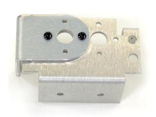 Figure 1.
Attach a Passive Hinge bracket to the "L" bracket as shown, using two 2-56 x .250 screws and 2-56 nuts.
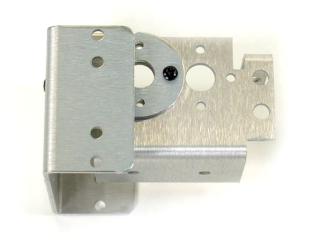 Figure 2.
Attach the ball bearing that comes with the Long "C" bracket to the Multi-Purpose bracket as shown. See the diagram below for detailed information.
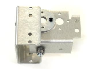 Figure 3-2.
Attach the "C" bracket to the Passive Hinge bracket as shown, using two ball bearings. See the diagram below for detailed information.
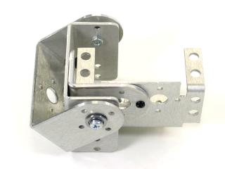 Figure 4-2.
Attach another "C" bracket to the "C" bracket already there, using two 2-56 x .250 screws and 2-56 nuts.
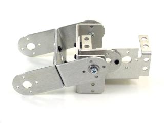 Figure 5.
Attach the "C" bracket to a Multi-Purpose bracket as shown. See the diagram below for detailed information.
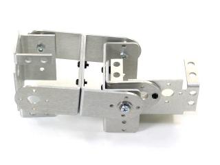 Figure 6-2.
Attach a Tubing Connector Hub to an "L" bracket as shown, using two 2-56 x .250 screws and 2-56 nuts.
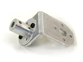 Figure 7.
Attach the other side of the "L" connector bracket to the Multi-Purpose bracket as shown, using two 2-56 x .250 screws and 2-56 nuts.
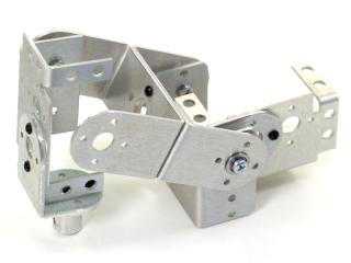 Figure 8.
Connect a 3.0" tube to the hub using a 4-40 x .250" screw. Attach a rubber foot to the end of the tube.
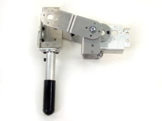 Figure 9-2.
Use 1.5" of 4-40 threaded rod to make a "dog bone" with a black plastic socket at each end. Attach the dog bone to the Multi-Purpose bracket and the Passive Hinge bracket as shown. See the diagram below for detailed information.
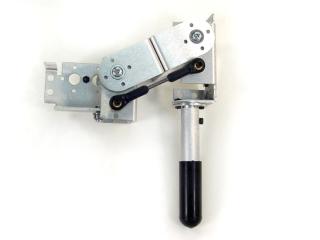 Figure 10-2.
Install the servos as shown, using the included 3mm hardware, and two #2 tapping screws. For quick prototype assembly, you can use rivet fasteners (sold separately: NSRF-01) as illustrated.
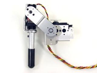 Figure 11.
You can adjust the angle of the leg by changing the length of the dog bone.
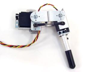 Figure 12.
By adding a spring, the joint can be load-balanced. This is a trade-off because when the leg is in the Down position, the load on the servo is reduced. However, the load when the leg is in the Up position is increased.
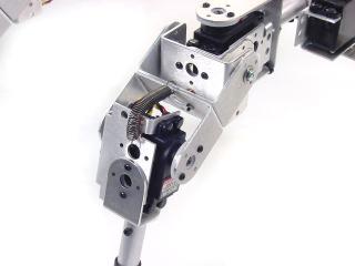 Figure 13.
Now the leg is ready to be attached to a body. Use two #2 tapping screws. These parts are included in the lexan chassis kits or the Long "C" brackets for an aluminum chassis.