
3DoF Lexan C Leg Lights Assembly Instructions v1.0
3DOFC Leg Lights Assembly Guide
Updated June 20, 2007
Safety first! Wear eye protection and never touch a powered robot!
Note: Do not use Loctite or thread locks on the assembly. They are not necessary and may cause damage to the Lexan.
The leg light kit includes 6 laser-cut acrylic parts that fit inside the 3DOFC legs. The kit does not include the 3mm LEDs, resistors, tape, heatshrink, or wires — these must be purchased separately. We used the RL3-R5014, 5000mcd Red LED from http://www.superbrightleds.com. If you substitute, use the brightest LEDs possible for best results.
After removing the protective covering from the parts, lightly sand them using 400 grit sandpaper. Make circular motions until the parts appear opaque. This will make the entire part glow when illuminated.
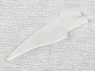 Figure 1.
Use white 1/8" wide tape to fully surround the edges of the parts. This prevents the light from escaping through the edges and reflects the light back into the part. White paint can also be used as an alternative.
Note: The tape should surround the part, but NOT cover the inside of the LED slot!
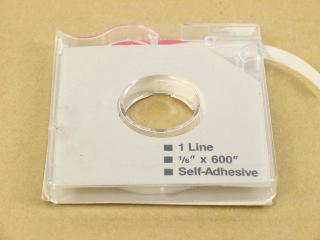 Figure 2.
This image shows the three stages of part preparation: the untouched part with protective coating removed, then the sanded part, then the tape-finished part.
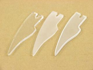 Figure 3.
Now it's time to wire the leg lights. Use 24AWG wire, a 1/8 watt resistor, and 3/32" heat shrink. The value of the resistor will depend on the supply voltage you use and the current rating of the LED.
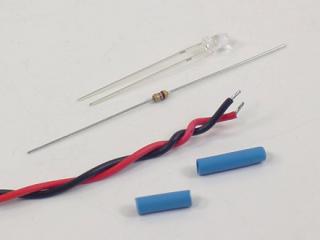 Figure 4.
Wire the LED as shown. Refer to the wiring diagram below for details.
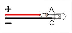
Wiring Diagram.
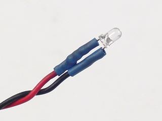 Figure 5.
Slide the LED into the cutout of the finished part.
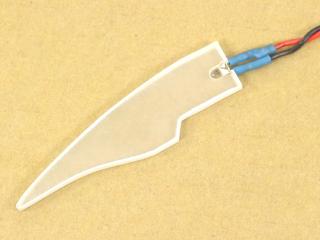 Figure 6.
If your leg is already assembled, remove the rubber end cap and bottom screw completely, then loosen the bottom two servo-mounting screws. Slide the finished light assembly in as shown — the point of the light assembly will rest just inside the lower part of the opening in the leg assembly.
It's a tight but precise fit; it may take some wiggling to align it. Reinstall the screw and rubber end cap, and tighten the servo-mounting screws.
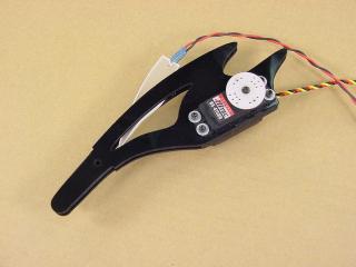 Figure 7.
Done — now make five more! Repeat steps 1–7 for each remaining leg.
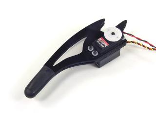 Figure 8.