
3DoF Lexan Leg Assembly Instructions v3.0
3 DOF Leg Assembly Instructions Rev. 3
Updated December 20, 2011
Safety first! Wear eye protection and never touch a powered robot!
Note: Do not use Loctite or thread locks on the assembly. They are not necessary and may cause damage to the Lexan.
Important! You need to build three right legs (following these instructions) and three left legs (by mirroring these instructions)!
The lexan pieces have a protective covering that needs to be removed before assembly. When the laser cuts, the covering melts into the cut edge which can make removal difficult. If you gently scrape the cut edge with a flat blade screwdriver, the covering can easily be lifted and peeled off.
On smaller pieces the coverings can be more difficult to remove. If you have trouble you can gently scrape the cut edge, then use duct tape to lift the covering off.
For further information on lexan, see this page.
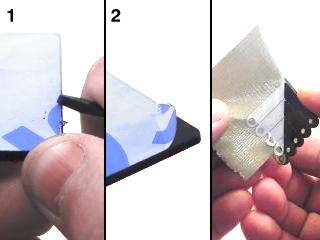 Lexan Preparation.
Drop the servo in through the hole. The servo tabs should be on top of the Lexan.
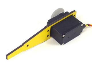 Figure 1.
Install the second lexan piece.
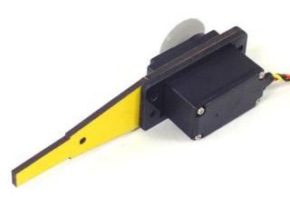 Figure 2.
Install the other long leg piece.
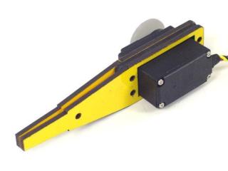 Figure 3.
Attach the servo to the lexan pieces using four 4-40 x .750" screws, steel washers, and nylon insert lock nuts. Position the washers on top of the servo's mounting tabs as shown.
 Figure 4.
Slide the small leg piece in between the long ones as shown, and attach it using a 4-40 x .500" hex screw and nylon insert lock nut.
 Figure 5.
You might want to use sandpaper to smooth off the edges of the bottom of the foot. It will be easier on the rubber end cap if you do.
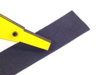 Figure 6.
Slide the robot foot rubber end cap onto the end of the leg. It might be a tight fit, but if you wiggle it, it will fit.
 Figure 7.
Peel the white cover off of the tape and press the tape onto the hinge as shown.
 Figure 8.
Clean the bottom of the servo with alcohol and allow it to dry. Then peel the green plaid cover off the tape on the hinge, and line the hinge up with the edge of the servo. Press the hinge onto the servo very firmly for a full ten seconds to ensure a good bond.
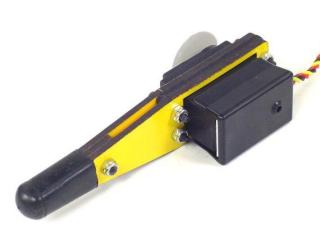 Figure 9.
Attach a ball bearing to the multi-purpose bracket as shown. Refer to Figure 10-1 for detailed information. Note: this ball bearing is part of the chassis kit or "C" bracket, if used.

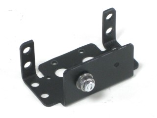 Figure 10-2.
Attach the two multi-purpose brackets as shown, using two 2-56 x .250" screws and 2-56 nuts.
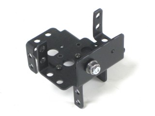 Figure 11.
Attach the two "C" brackets as shown, using two 2-56 x .250" screws and 2-56 nuts.
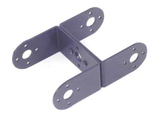 Figure 12.
Attach the "C" bracket to the multi-purpose bracket as shown. Refer to Figure 13-1 for detailed information.
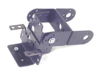 Figure 13-2.
Attach the servo as shown, using the included 3mm hardware. Make sure to route the servo wire as shown.
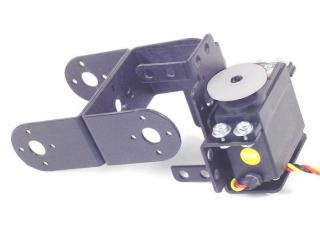 Figure 14.
Attach the servo as shown, using the included 3mm hardware. Make sure to route the servo wire as shown.
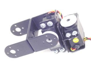 Figure 15.
Attach the servo to the "C" bracket using the #2 tapping screws and the diagram below. Make sure that the servo is centered before attaching to the "C" bracket.
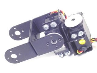 Figure 16.
Install the servo as shown using the #2 tapping screws and the diagram below. Make sure that the servo is centered before attaching to the "C" bracket.
 Figure 17.
Attach the "C" bracket to the servo hinge as shown. Refer to Figure 18-1 for detailed information. Make sure to route the servo wire as shown — leave enough slack for the leg to freely move without pulling on the servo wire.
You can now move on to the body assembly instructions.
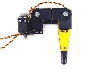 Figure 18-2.