
3DoF Leg Assembly Instructions v2.0
3 DOF A Leg Assembly Instructions v2.0
Updated August 30, 2007
Safety first! Wear eye protection and never touch a powered robot!
Note: Do not use Loctite or thread locks on the assembly. They are not necessary and may cause damage to the Lexan or plastic.
Important! You need to build a right leg for every left leg by mirroring these instructions!
Attach a ball bearing to the Multi-Purpose bracket as shown. See the figure below for detailed information.
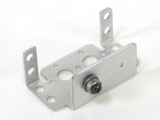 Figure 1-2.
Attach the Multi-Purpose bracket from step 1 to another Multi-Purpose bracket as shown, using two 2-56 x .250 screws and 2-56 nuts.
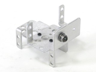 Figure 2.
Attach two "C" brackets together, using two 2-56 x .250 screws and 2-56 nuts.
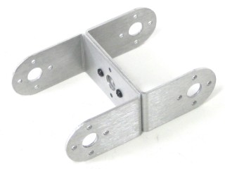 Figure 3.
Attach the "C" bracket to the Multi-Purpose bracket from step 2 as shown. See the figure below for detailed information.
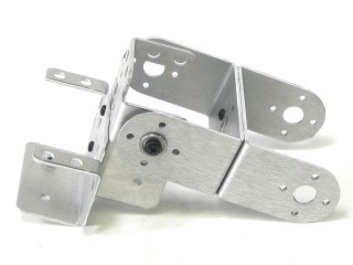 Figure 4-2.
Attach a Tubing Connector Hub to an "L" bracket as shown, using two 2-56 x .250 screws and 2-56 nuts.
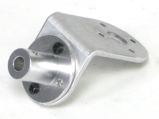 Figure 5.
Attach the other side of the "L" connector bracket to the Multi-Purpose bracket as shown, using two 2-56 x .250 screws and 2-56 nuts.
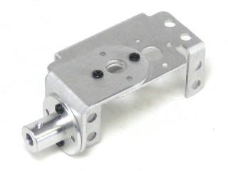 Figure 6.
Attach the Multi-Purpose bracket to a "C" bracket as shown, using two ball bearings. See the figure below for detailed information.
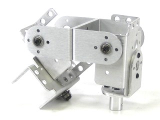 Figure 7-2.
Install the servos as shown, using the included 3mm hardware and #2 tapping screws.
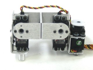 Figure 8.
Connect a 3.0" tube to the hub using a 4-40 x .250" screw. Attach a rubber foot to the end of the tube.
Be sure to mirror the other leg for symmetry. Once complete, you can move on to the body assembly instructions.
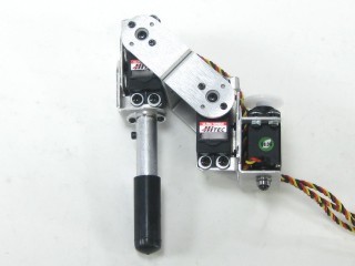 Figure 9-2.