
3DoF Leg Assembly Instructions v1.0
3 DOF Leg Assembly Instructions
Updated August 30, 2007
Safety first! Wear eye protection and never touch a powered robot!
Note: Do not use Loctite or thread locks on the assembly. They are not necessary and may cause damage to the Lexan.
Important! If you are building legs for the EH3-R using the Bot Board / Basic Atom 28 and SSC-32, you need to build three right legs and three left legs. This is also true for a standard insect-looking hexapod such as the EH3. However, if you are building for the EH3-R using the ServoPod, you need to make 6 right legs.
Attach an "L" connector bracket to a Multi-Purpose bracket as shown, using two 2-56 x .250 screws and 2-56 nuts.
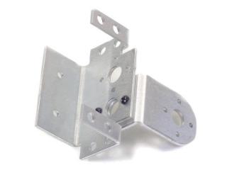 Figure 1.
Attach a Multi-Purpose bracket to the "L" bracket as shown, using two 2-56 x .250 screws and 2-56 nuts.
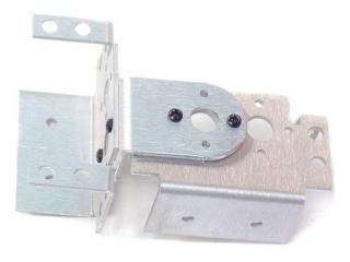 Figure 2.
Attach the ball bearing that comes with the Long "C" bracket or Lexan chassis to the Multi-Purpose bracket as shown. See the diagram below for detailed information.
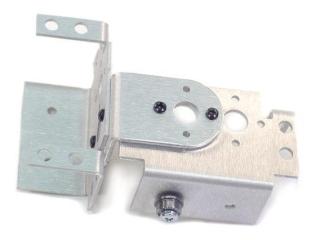 Figure 3-2.
Attach the "C" bracket to the Multi-Purpose bracket as shown. See the diagram below for detailed information.
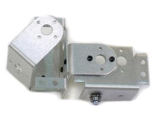 Figure 4-2.
Attach another "C" bracket to the "C" bracket already there, using two 2-56 x .250 screws and 2-56 nuts.
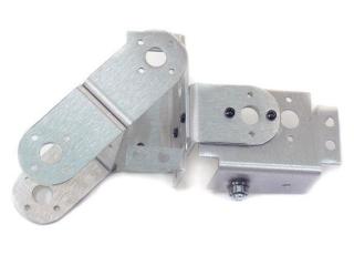 Figure 5.
Attach the "C" bracket to a Multi-Purpose bracket as shown, using two ball bearings. See the diagram below for detailed information.
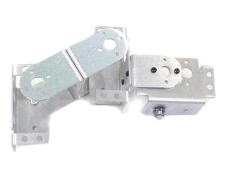 Figure 6-2.
Attach a Tubing Connector Hub to an "L" bracket as shown, using two 2-56 x .250 screws and 2-56 nuts.
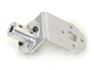 Figure 7.
Attach the other side of the "L" connector bracket to the Multi-Purpose bracket as shown, using two 2-56 x .250 screws and 2-56 nuts.
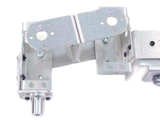 Figure 8.
Connect a 3.0" tube to the hub using a 4-40 x .250" screw. Attach a rubber foot to the end of the tube.
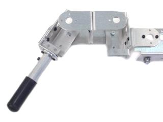 Figure 9-2.
Install the servos as shown, using the included 3mm hardware and two #2 tapping screws. For quick prototype assembly, you can use rivet fasteners (sold separately: NSRF-01) as illustrated.
You can now move on to the body assembly instructions.
 Figure 10.