
A-Pod 3DoF Tail Assembly Instructions
The A-POD Tail Assembly Guide
Updated November 4, 2011
Removing the Parts from the Panel
The PVC parts need to be carefully cut out of the panel. A thin, flat blade exacto knife will be very helpful. Simply cut through the tabs to remove the parts.
Important!
DO NOT overtighten screws on the PVC parts! The PVC will compress and will become weaker as a result.
Preparation
Remove the nylon servo horn from each servo and replace with a metal servo horn. Be sure to keep it in the same orientation.
Attach a ball bearing to a Multi-purpose bracket as shown. See the diagram below for detailed information. Make two of these.
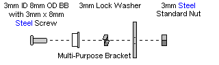
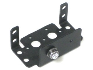 Figure 1.
Attach the two brackets together as shown using two 2-56 x .25" screws and two 2-56 nuts.
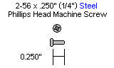
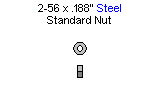
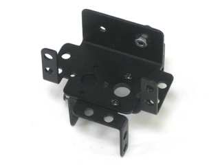 Figure 2.
Attach four 1.0" hex spacers to the "bad" side of the top panel with four 4-40 x .375" screws.

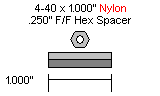
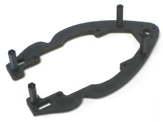 Figure 3.
Using four 4-40 x .250" hex socket head screws, attach four 0.75" hex spacers to the Bot Board II as shown. Insert the Basic Atom Pro 28 chip into the socket.
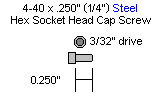
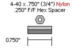
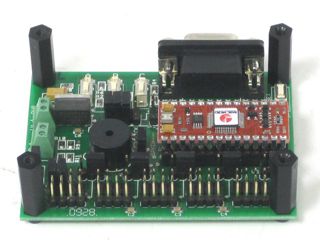 Figure 4.
Attach the Bot Board II to the top panel of the tail using four 4-40 x .375" screws.
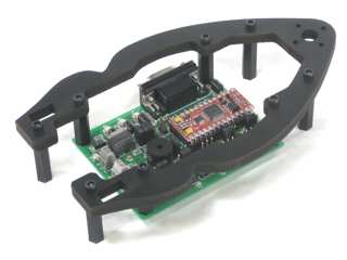 Figure 5.
Slide the two "T" shaped PVC pieces into the slots as shown. Attach the bottom panel using four 4-40 x .375" hex screws.
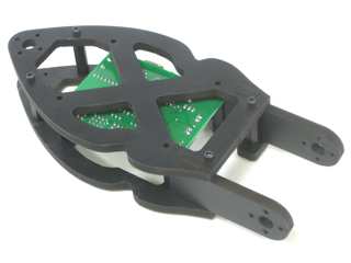 Figure 6.
Slide the bracket assembly into place as shown.
.jpg) Figure 7.
Figure 7.
Slide a HS-645MG servo into the bracket and secure it using 3mm hardware as shown. Attach it to the PVC with four 2-56 x .375" screws.
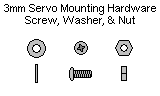
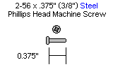
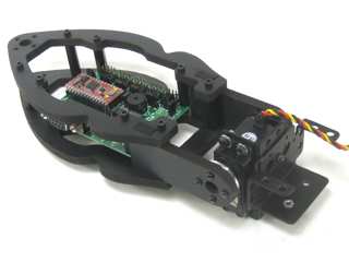 Figure 8.
Slide the tail assembly in place in the rear of the chassis.
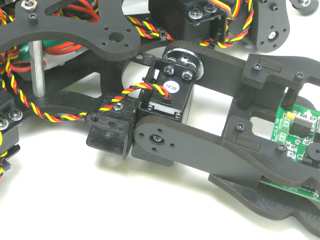 Figure 9.
Attach a HS-645MG to the robot using 3mm screws, washers and nuts. Connect the servo horn to the chassis using four 2-56 x .375" screws.
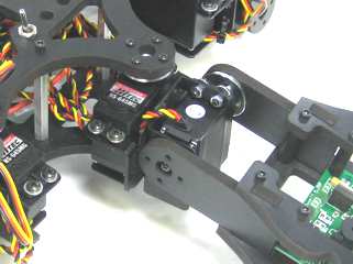 Figure 10.