
BH3 3DoF Body Assembly Instructions v2.0
BH3 Body Assembly Instructions Rev. 1
Updated January 28, 2009
Safety first! Wear eye protection and never touch a powered robot!
The purpose of this guide is to construct the chassis, attach the legs, and install the electronics. As long as the servo horns have not been removed from the servos, you do not have to center them during the assembly process.
Use eight 4-40 x 1/4" hex socket screws to attach the spacers to the bottom of the robot.
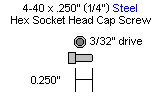
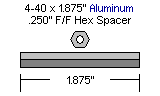
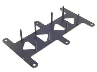 Figure 1.
Mount the top of the robot using eight 1/4" hex screws.
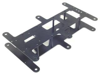 Figure 2.
Slide the end panels in as shown, and attach using eight 3mm x 6mm screws.
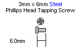
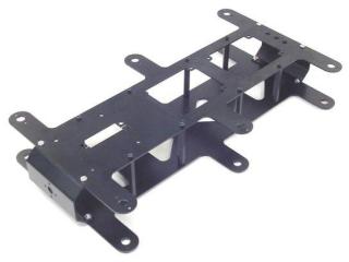 Figure 3.
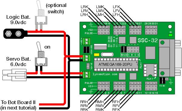
The SSC-32 should be configured for 115.2 kbaud and DB9 communication, with the VS2=VS1 jumper installed. Remove the VL=VS jumper. Consult the SSC-32 manual if needed. Attach the wiring harness to VS1. Connect 8" of 24AWG wire (not included) AND the 9V battery clip to VL to provide power for the electronics. For now, put electrical tape on the end of the wire. Make sure red wires go to (+) and black wires go to (−). Use four 1/4" hex screws to attach four 3/4" nylon hex spacers to the SSC-32 as shown.
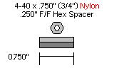
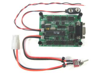 Figure 4.
Install the Atom 28 as shown, taking care not to damage the delicate pins. Remove the following jumpers: VS=VL, ABC buttons / LED. Install the following jumpers: speaker enable, VL to I/O 4-7 bus. Consult the Bot Board manual if needed. Use four 1/4" hex screws to attach four 3/4" nylon hex spacers to the Bot Board as shown.
 Figure 5.
Schematic. Double check your connections against the schematic below.
| Servo Letter Definitions | ||
|---|---|---|
| Left Right |
Rear Middle Front |
Knee Vertical Horizontal |
Schematic 5-1.
Slide the SSC-32 in from the top, orient as shown with the DB9 connector toward the front, and attach using four 1/4" hex screws. At this point, attach the power switch to the robot's body using any of the holes the switch will reach.
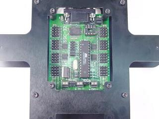 Figure 6.
Attach the power wires from the SSC-32 to the Bot Board's VL input as shown. Make sure the red wire goes to (+) and the black wire goes to (−).
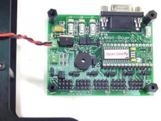 Figure 7.
Slide the Bot Board in from the top, orient as shown with the power terminals toward the rear, and attach using four 1/4" hex screws.
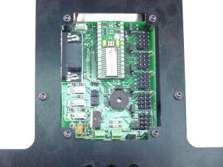 Figure 8.
Attach the legs as shown, making sure to use right or left legs as indicated. Use twelve #2 x .250" tapping screws.
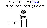
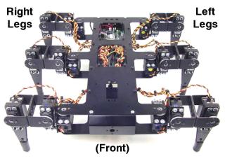 Figure 9.
Plug the servos into the SSC-32 as illustrated in Figure 10. Simply plug in the servo associated with the function to the corresponding pin. If oriented correctly, the I/O port (group of four pins) will be closest to its corresponding leg.
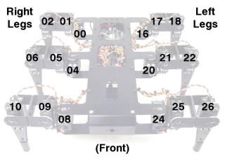 Figure 10.
This completes the mechanical assembly. You can now move on to the Complete H3/H3-R Tutorial.
 Figure 11.