
Heavy Duty Metal Arm Base Assembly
Heavy Duty Metal Arm Base Assembly
Updated August 24, 2011
Safety first! Wear eye protection and never touch a powered robot!
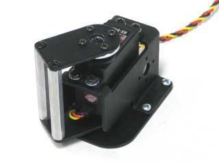
Completed base.
Attach a ball bearing to the base plate as shown. The screw should be flush with the base plate.
Figure 1-1 — Ball bearing diagram.
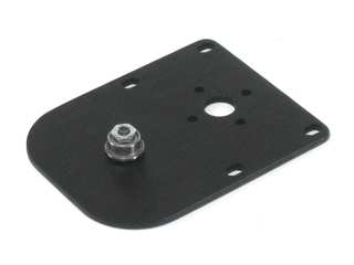 Figure 1-2.
Construct a heavy-duty "C" bracket using two aluminum standoffs and the two metal plates as shown. Use four 4-40 x .375" machine screws. The screws should be flush with the plates when done.

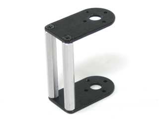 Figure 2.
Stack the servo bracket on top of the base plate and attach them to a piece of wood using #4 tapping screws. Do not tighten all the way yet. Alternatively, use four 4-40 x .375" screws and nuts if not attaching to wood.
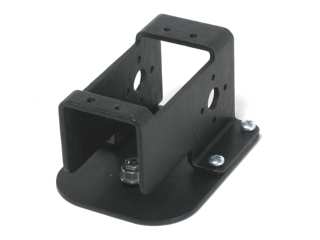 Figure 3.
Remove the HS-645MG's plastic servo horn and replace it with the metal one. Be sure to install the new horn in the same orientation as the old one!
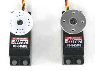 Figure 4.
Slide the HS-645MG servo into the bracket and secure it with four 3mm x 6mm screws and washers. Note: the bracket is tapped — nuts are not required.
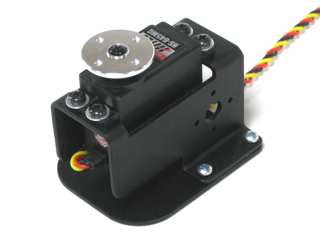 Figure 5.
Slide the "C" assembly into position over the ball bearing and servo horn. If building an arm kit, attach your ASB-201 (AL5A / AL5B) or ASB-204 (AL5D) to the "C" bracket using four 2-56 x .250" screws. Otherwise, simply attach the "C" bracket to the servo horn. Note: the bracket is included in the arm kit, not the base kit.
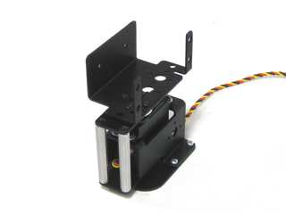 Figure 6.