Biped BRAT Jr. Assembly Guide
| Biped BRAT Jr. Assembly Guide. Updated 08/06/2009.
Hardware: |
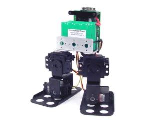 Image of Biped BRAT Jr. |
||||||||||||
| Step 1. Attach a multi-purpose bracket to the foot as shown, using three 2-56 x .188" screws and 2-56 nuts.
|
 Figure 1. |
||||||||||||
| Step 2. Attach the "L" bracket to a short "C" bracket as shown, using two 2-56 x .250" screws and 2-56 nuts.
|
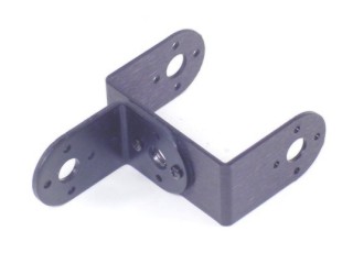 Figure 2. |
||||||||||||
| Step 3. Attach a multi-purpose bracket to the "L" bracket as shown, using two 2-56 x .250" screws and 2-56 nuts.
|
 Figure 3. |
||||||||||||
| Step 4. Attach the assembly from Step 3 to the multi-purpose bracket on the foot. See figure 4-1 for detailed information.
|
 Figure 4-2. |
||||||||||||
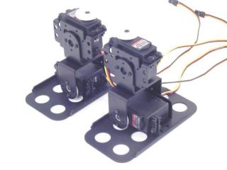
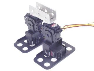
| Step 5. Your two leg assemblies should look like the image so far. |
 Figure 5. |
||||||||||||
| Step 7. Install the servos as shown, using the included 3mm hardware, two #2 tapping screws and the diagram below. For quick prototype assembly, you can use rivet fasteners (sold separately: NSRF-01) as illustrated.
|
|
||||||||||||
| Step 8. Attach the leg assemblies to the 3" U-Channel as shown, using four #2 tapping screws.
|
|
||||||||||||
| Step 10. Attach the 3/4" standoffs to the electronics carrier using four 4-40 x 1/4" hex socket head cap screws.
|
|
||||||||||||
| Step 11. Attach the 5/16" standoffs to the U-Channel as shown, using two 2-56 x 1/4" screws.
|
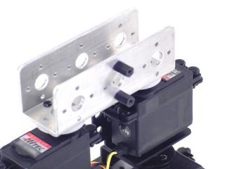 Figure 11. |
||||||||||||
| Step 12. Attach the electronics carrier as shown, using two 2-56 x 1/4" screws.
|
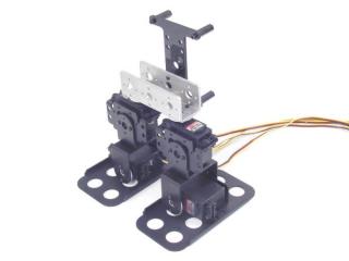 Figure 12. |
||||||||||||
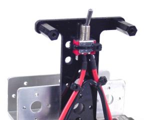
| Step 13. Attach the power switch to the electronics carrier as shown. |
|
||||||||||||
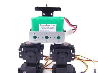
| Step 14. Your battery can be attached with a wire tie or Velcro, not included. A 6vdc battery will power the robot fine, however, as the battery discharges, the SSC-32 will reset even though there is still sufficient power for the servos. A 7.2vdc battery will lessen this effect, but it is slightly harder on the servos. For maximum run time, power the VL input from a separate 9vdc battery. Remember to remove the VS=VL jumper to isolate the two supplies. The 6 or 7.2vdc battery is still required! |
|
||||||||||||
| Step 15. Install the SSC-32 using four 4-40 x 1/4" screws. Make sure to orient the SSC-32 as shown.
|
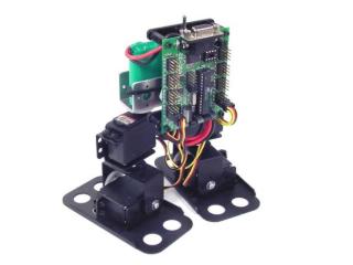 Figure 15. |
||||||||||||
| Step 16. Connect the servos to their appropriate I/O channels on the SSC-32. Consult Table 20, and make sure to check your work. Connect the wiring harness to VS1 or VS2 on the SSC-32 as shown. Note, red is (+) and black is (-). If you like, you can flip the SSC-32 around to protect the wires and take up less space.
|
|
||||||||||||


