
Biped BRAT Jr. Assembly Guide
Biped BRAT Jr. Assembly Guide
Updated August 6, 2009
Hardware: 1x Alum. Channel 3" Single Pack (ASB-503) · 2x Multi-Purpose Servo Bracket Two Pack (ASB-04) · 1x "L" Connector Bracket Two Pack (ASB-06) · 1x "C" Servo Bracket w/ Ball Bearings Two Pack (ASB-09) · 1x Robot Feet Pair (ARF-01) · 1x SES Electronics Carrier (EC-02) · 1x SSC-32 Servo Controller · 4x HS-422 Standard Servo (S422)
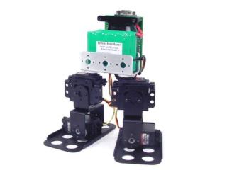
Biped BRAT Jr.
Attach a multi-purpose bracket to the foot as shown using three 2-56 x .188" screws and 2-56 nuts.
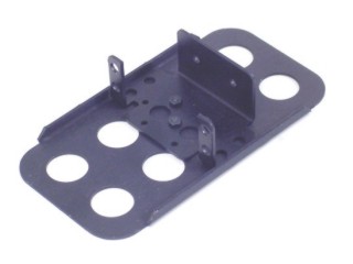 Figure 1.
Attach the "L" bracket to a short "C" bracket as shown using two 2-56 x .250" screws and 2-56 nuts.
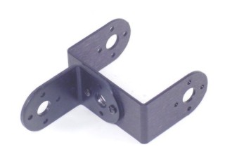 Figure 2.
Attach a multi-purpose bracket to the "L" bracket as shown using two 2-56 x .250" screws and 2-56 nuts.
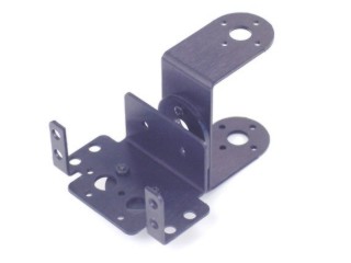 Figure 3.
Attach the assembly from Step 3 to the multi-purpose bracket on the foot. Refer to Figure 4-1 for detailed ball bearing installation.
 Figure 4-1 (ball bearing detail).
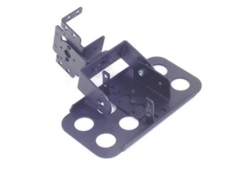 Figure 4-2.
Your two leg assemblies should look like the image at this point. Repeat Steps 1–4 for the second leg.
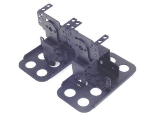 Figure 5.
Install the servos as shown using the included 3mm hardware and two #2 tapping screws per the diagram. For quick prototype assembly, rivet fasteners (NSRF-01, sold separately) can also be used.
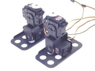 Figure 6.
Attach the leg assemblies to the 3" U-Channel as shown using four #2 tapping screws.
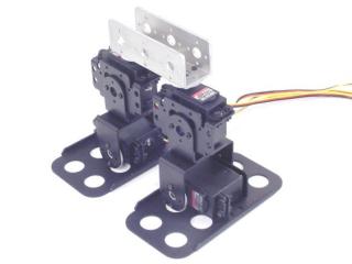 Figure 7.
Attach the 3/4" standoffs to the electronics carrier using four 4-40 x 1/4" hex socket head cap screws.
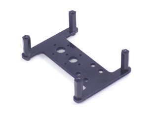 Figure 8.
Attach the 5/16" standoffs to the U-Channel as shown using two 2-56 x 1/4" screws.
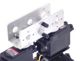 Figure 9.
Attach the electronics carrier as shown using two 2-56 x 1/4" screws.
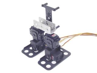 Figure 10.
Attach the power switch to the electronics carrier as shown.
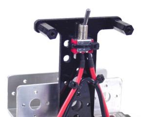 Figure 11.
Your battery can be attached with a wire tie or Velcro (not included).
A 6VDC battery will power the robot fine, however as it discharges the SSC-32 may reset even though there is still sufficient power for the servos. A 7.2VDC battery lessens this effect but is slightly harder on the servos.
For maximum run time, power the VL input from a separate 9VDC battery. Remember to remove the VS=VL jumper to isolate the two supplies — the 6V or 7.2V battery is still required.
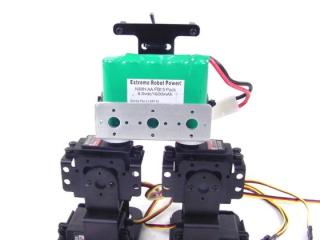 Figure 12.
Install the SSC-32 using four 4-40 x 1/4" screws — orient it as shown. Connect the servos to their appropriate I/O channels per Table 16. Connect the wiring harness to VS1 or VS2 on the SSC-32 (red = +, black = −).
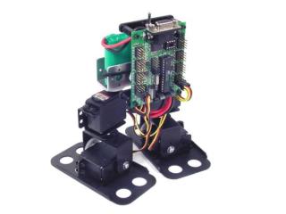 Figure 13.
SSC-32 Servo Channel Assignments (Table 16)
| SSC-32 I/O | Servo |
|---|---|
| 00 | Right Ankle |
| 01 | Right Hip |
| 16 | Left Ankle |
| 17 | Left Hip |