
Scout Biped Torso Assembly Instructions Rev. 2
Biped Scout Torso Assembly Guide — Rev. 2
Updated December 21, 2011
Safety first! Wear eye protection and never touch a powered robot!
Note: Do not use Loctite or thread locks on the chassis assembly — they are not necessary and may cause damage to the Lexan.
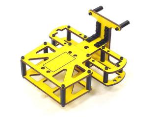
Completed Biped Scout Torso.
Remove the protective covering from all Lexan pieces before assembly. The laser cutting process melts the covering into the cut edge, making removal harder. Gently scrape the cut edge with a flat blade screwdriver to lift and peel the covering off.
On smaller pieces, use duct tape to lift the covering after scraping. For more information on Lexan, see this page.
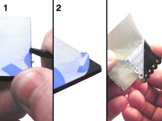 Lexan preparation.
Attach six 3/4" spacers to the bottom panel of the torso using six 4-40 x 3/8" screws. This panel has no designated front or back.

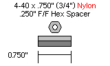
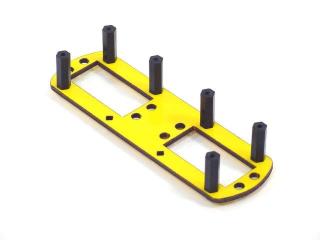 Figure 1.
Attach the top torso panel using six 4-40 x 3/8" screws.
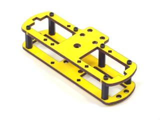 Figure 2.
Slide two 3/4" spacers between the torso panels and use two 4-40 x 3/8" screws to attach the bottom nose panel.
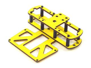 Figure 3.
Attach four 1" spacers to the bottom nose panel using four 4-40 x 3/8" screws.
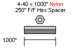
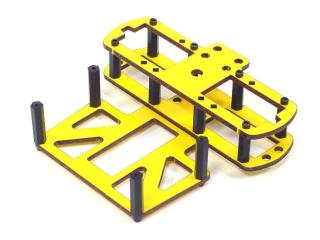 Figure 4.
Use six 4-40 x 3/8" screws to attach the top nose panel.
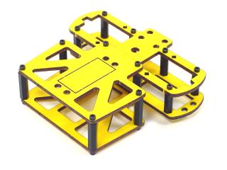 Figure 5.
Use four nylon rivet fasteners to attach two "L" brackets to the top of the torso as shown.
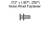
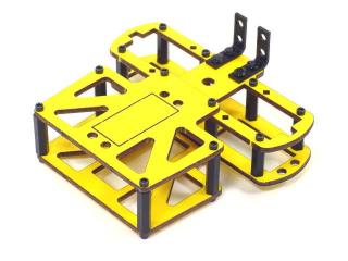 Figure 6.
Attach four 3/4" spacers to the electronics backpack using four 4-40 x 1/4" screws. The remaining four 1/4" screws are reserved for connecting the microcontroller board after final assembly.
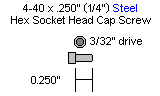
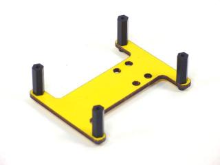 Figure 7.
Use four rivet fasteners to attach the electronics backpack to the rear of the torso as shown, with the short end facing up.
Figure 8 (completed torso).