
Lynx B - Pan and Tilt Assembly Instructions v2.0
Last modified by Eric Nantel on 2026/04/02 15:25
Lynx B - Pan and Tilt Assembly Instructions Rev. 2
Updated December 21, 2011
Safety first! Wear eye protection and never touch a powered robot!
Lynx B Pan and Tilt — Assembly
Step 1 / 5
Attach the multi-purpose servo bracket to one servo as pictured.
2x
#2 x .250" tapping screw

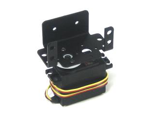 Figure 1.
Lynx B Pan and Tilt — Assembly
Step 2 / 5
Attach the "C" servo bracket to the multi-purpose bracket as shown. Push the button head screw through the multi-purpose bracket, and add a nylon washer. Put the "C" bracket on the screw, and secure it with the nylon acorn nut. Don't make this too tight!
1x
Hardware set (screw, washer, acorn nut)
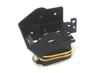 Figure 2.
Lynx B Pan and Tilt — Assembly
Step 3 / 5
Install the servo into the multi-purpose bracket. Use four push-in fasteners.
4x
Push-in fastener
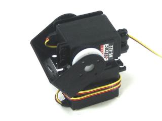 Figure 3.
Lynx B Pan and Tilt — Assembly
Step 4 / 5
Attach the "C" bracket to the servo as pictured.
2x
#2 x .250" tapping screw
1x
Hole reference diagram
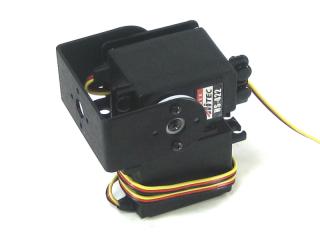 Figure 4.
Lynx B Pan and Tilt — Assembly
Step 5 / 5
Any small CCD camera can be attached to the Pan and Tilt assembly. The mounting plate is 2.0" wide by 1.0" high, and the entire surface can be used. The camera can be attached with double sided tape.
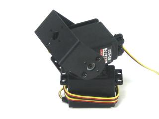 Figure 5.