A4WD1 & AL5 Arm Tutorial for PS2 Control (BotBoarduino)
| A4WD1
Tutorial for PS2 Control v1.0 (This document can also be used as a basis for the BotBoarduino Autonomous Kit) Updated 04/05/2012 Safety first! Wear eye protection and never touch a powered robot! Note: Do not use Loctite or thread locks on the assembly. They are not necessary and may cause damage to the Lexan. Note: This guide follows the assembly guide. The Sabertooth has already been installed. Software: |
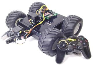 Image of A4WD1. |
||||||||||||||||||||
|
|
|||||||||||||||||||||
Step
1. Mounting the BotBoarduino
|
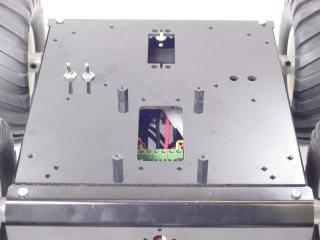 Figure 1. |
||||||||||||||||||||
Step
2.
|
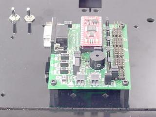 Figure 2. Add the Microcontroller (Bot Board or BotBoarduino) |
||||||||||||||||||||
| Step 3. Connecting Sabertooth to the BotBoarduino The Sabertooth 2x10 R/C was primarily designed to be connected to a remote control receiver. It has a BEC (battery elimination circuit) that puts 5vdc on the red wires to power the receiver. Because the BotBoarduino has its own power supply, it is necessary to bypass the BEC. Use an exacto knife to carefully pry the black tab up and slip the red wire out of the black housing as shown in Figure 3. Bend the red wires up and use electrical tape to cover them as shown. This will prevent accidental shorts. |
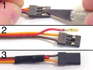 Figure 3. |
||||||||||||||||||||
| Step
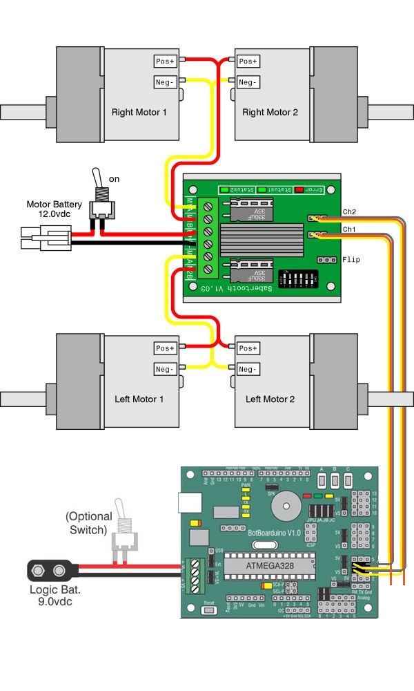
4. Refer to Table 4 and the schematic (Figure 5) for BotBoarduino and Sabertooth wiring connections. Double check your wiring. Make sure the red battery wire goes to the (+) terminal! |
|
||||||||||||||||||||
Step
5.
|
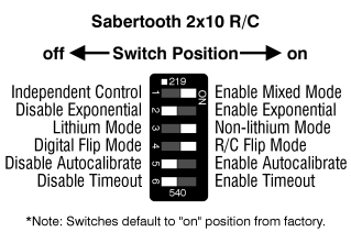 Figure 5. |
||||||||||||||||||||
|
Schematic - Figure 5. |
|||||||||||||||||||||
| Step
6. Programming the BotBoarduino Download the Arduino Software. Install and run the program on your PC. The goal here is to load a program into the editor and program the BotBoarduino with the code. |
|||||||||||||||||||||
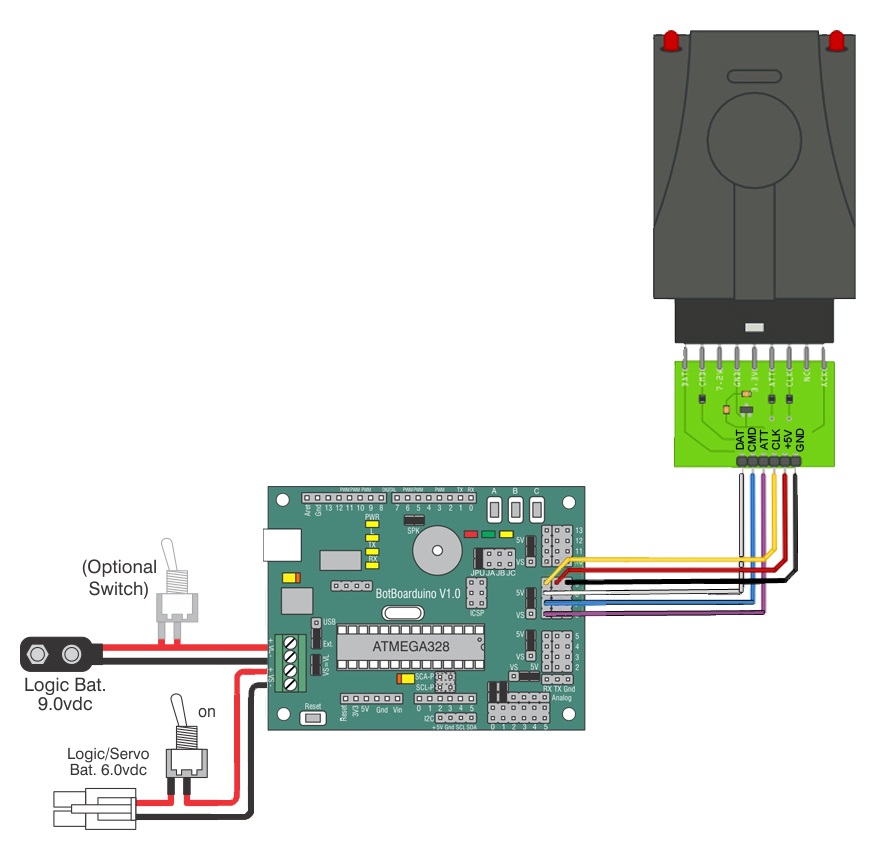
| Step 7. Now it's time to set up the A4WD1 for PS2 R/C control. The code supports a pan and tilt and gripper, but they are optional. The Pan and Tilt is installed on the front of the top panel, and the gripper is installed on the front of the base. If you are adding a pan and tilt and gripper, you will need to change the power bus jumpers according to Table 9 and Schematic 10. Note: Refer only to Figure 9 for connection information. The cable colors in the picture may be outdated. Note that the 6.0V power supply is only needed if you also plan to operate servos using the BotBoarduino.
|
|
||||||||||||||||||||
| Step
11. Copy and paste this text into the Arduino program (A4WD1 + PS2 Arduino Sample Code). Connect the BotBoarduino to the computer via USB cable. Within the Arduino program, under "Tools", select the board type (Arduino Duemilanove w/328) and COM port (This is computer specific). You will want to set the bot on something so that the wheels aren't touching the ground. Before running the program turn on the PS2 controller. When the program is run it will turn most PS2 game controllers to analog mode automatically. If your controller does not automatically go into analog mode, you will need to do so manually. |
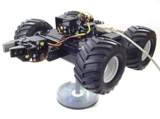 Figure 11. |
||||||||||||||||||||


