Stomper Sumo Assembly Instructions v2.0
Last modified by Eric Nantel on 2023/02/06 13:26
| Stomper
Online Assembly Instructions Rev.
2.
Updated 08/26/2004 Safety first! Wear eye protection and never touch a powered robot! Note: Do not use Loctite or thread locks on the chassis assembly. They are not necessary and may cause damage to the Lexan. |
 Stomper |
| Step 1. Install
the motors into the body panels using nine 3mm x 6mm machine screws for
each panel. The right side is illustrated in Figure 1. Mirror for the
other panel.
18 x |
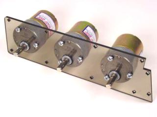 Figure 1. |
| Step 2. Mount the
two aluminum rails to the inside of the body panel above and below the
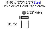
motors. Use eight 4-40 x 3/8" machine screws per panel.
16 x |
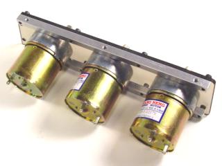 Figure 2. |
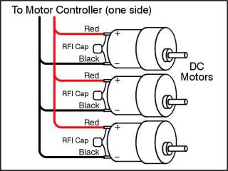
| Step 3. Wire your
motors now, as it will be difficult after the body assembly is complete.
Be sure to add the noise suppression capacitors. Wire each of the three
motors in parallel.
|
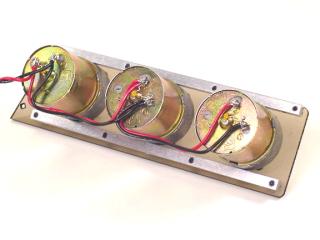 Figure 3. |
| Step 4. Install
the bottom panel using six 4-40 x 1/4" machine screws.
6 x |
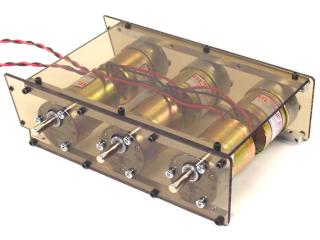 Figure 4. |
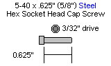
| Step 5. Attach
the hex spacers as shown using eight 4-40 x 3/8" screws for the
3/4" spacers, and four 4-40 x 1/4" machine screws for the
3/8" spacers.
8 x |
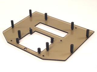 Figure 5. |
| Step 6. Install
the middle panel using six 4-40 x 1/4" machine screws.
6 x |
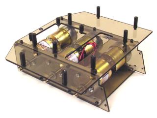 Figure 6. |
| Step 7. Install
the top panel using eight 4-40 x 3/8" machine screws.
8 x |
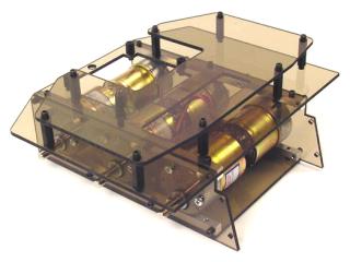 Figure 7. |
| Step 8. Mount the wheel hubs onto the motor shafts. Drive the set screws in until they make contact with the flat part of the shaft, then back off a bit. Next slide the hub towards the motor as far as it will go, then tighten the set screw tight. | 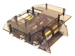 Figure 8. |
| Step 9. Install
the tires using two 5-40 x 5/8" machine screws per tire. Tighten them
down, but be careful not to overdue it, as you could damage the plastic
rim.
12 x |
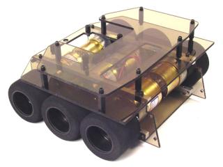 Figure 9. |
| Step 10. Mount
the two aluminum rails to the inside of the body panels as shown in
figure 10. Use four 4-40 x 3/8" machine screws.
4 x |
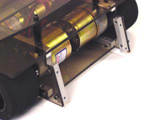 Figure 10. |
| Step 11. Install
the scoop using four 4-40 x 3/8" machine screws.
4 x |
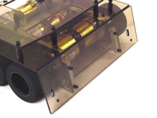 Figure 11. |
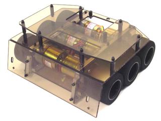
| This completes the assembly of the rolling chassis. Now you need to add your motor drivers, sensors and microcontroller. It is still a long way from being battle ready, but it's a great start! | Figure 12. |