LSS-P - Mechanical
Page Contents
Mounting Points | ||
 | ||
LSS-P-L1 There are 6 untapped holes and 6 tapped holes around the circumference of the gearbox. The tapped holes are used to fix the frame to the gearbox and are M4 tapped on a 65mm diameter circle. The untapped holes are 4.5mm diameter on a 96mm diameter circle with a depth of 7mm. Gearbox Output Mounting
Mounting Plate
| ||
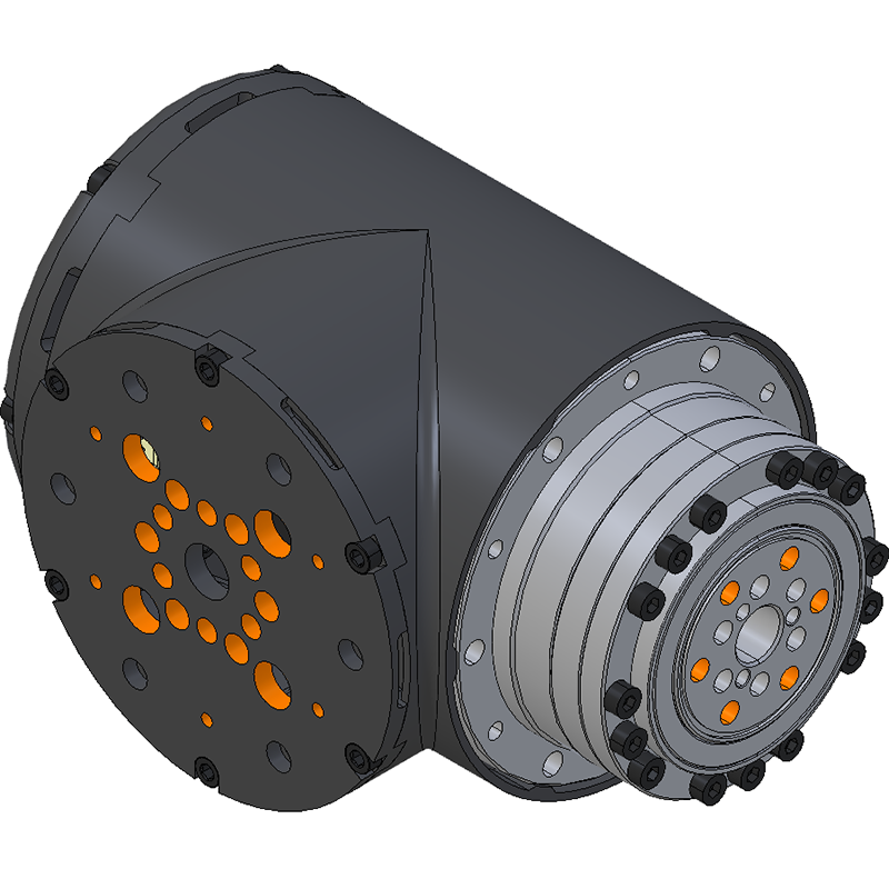 | ||
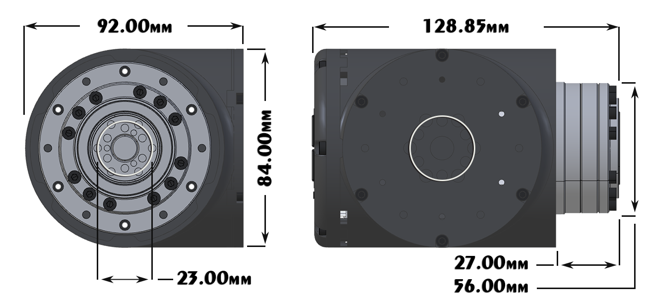
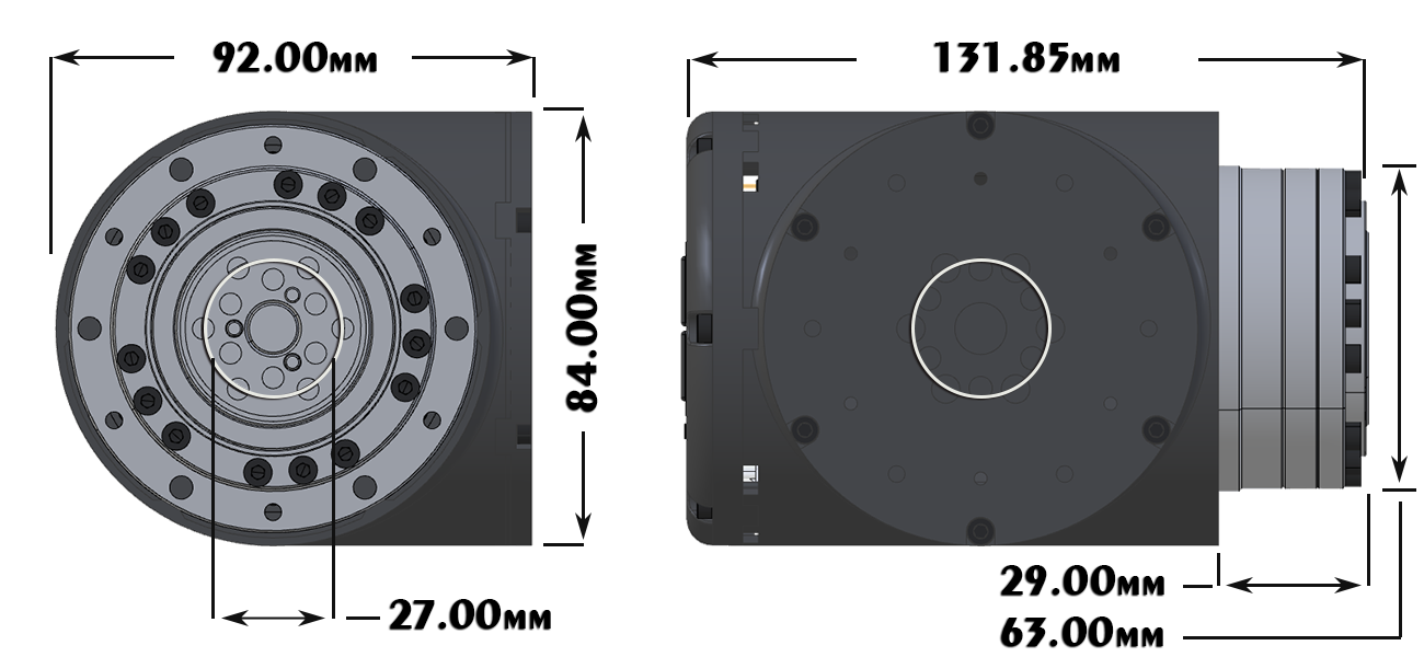
LSS-P-S1 There are 6 untapped holes and 6 tapped holes around the circumference of the gearbox. The tapped holes are used to fix the frame to the gearbox and are M4 tapped on a 71mm diameter circle. The untapped holes are 4.5mm diameter on a 71mm diameter circle with a depth of 7mm. Gearbox Output Mounting
Mounting Plate
| ||
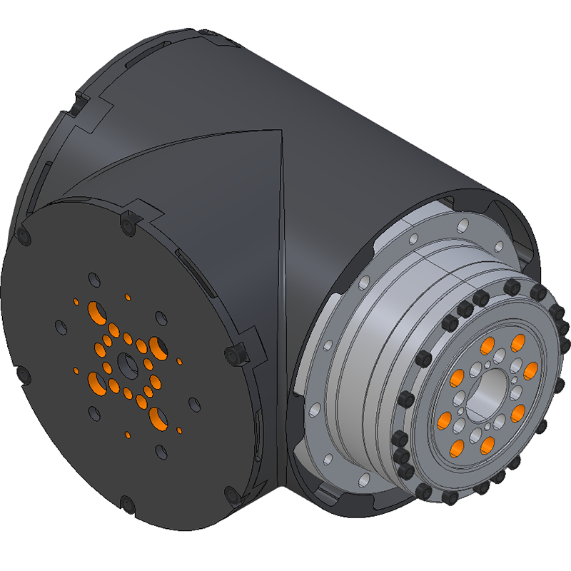 | ||
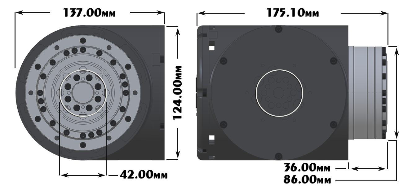
LSS-P-M1 There are 6 untapped holes and 6 tapped holes around the circumference of the gearbox. The tapped holes are used to fix the frame to the gearbox and are M5 tapped on a 96mm diameter circle. The untapped holes are 5.5mm diameter on a 96mm diameter circle. Gearbox Output Mounting
Mounting Plate
| ||
Case | ||
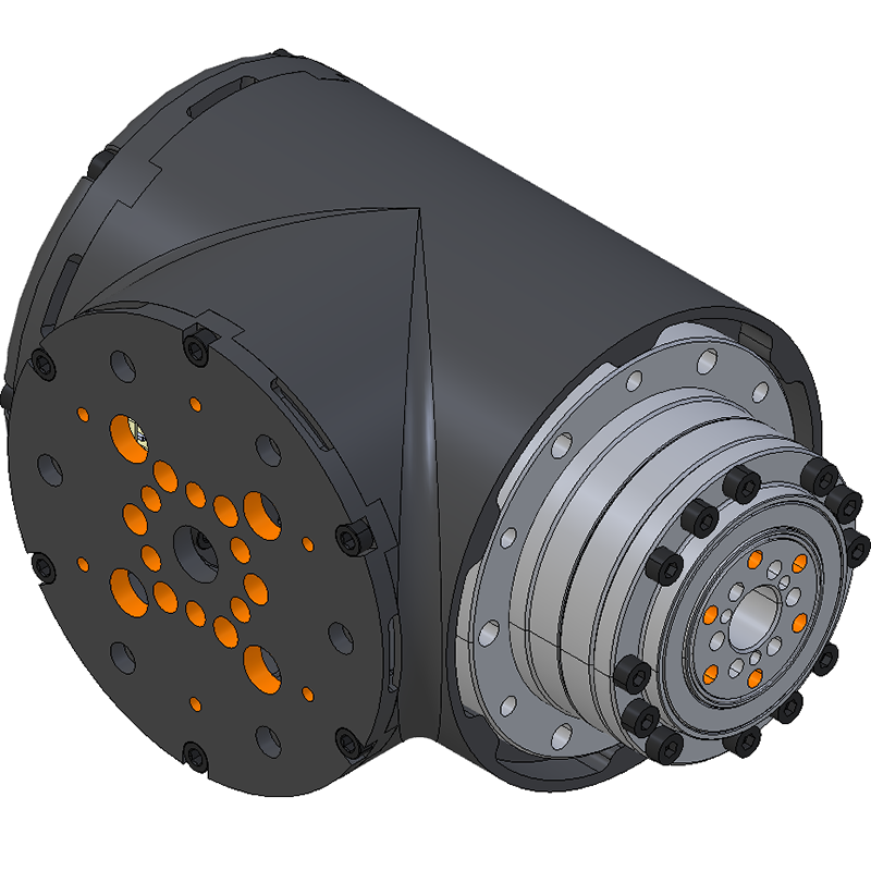
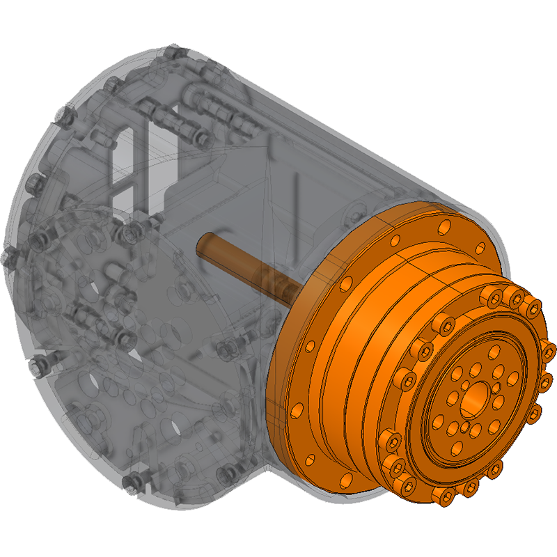
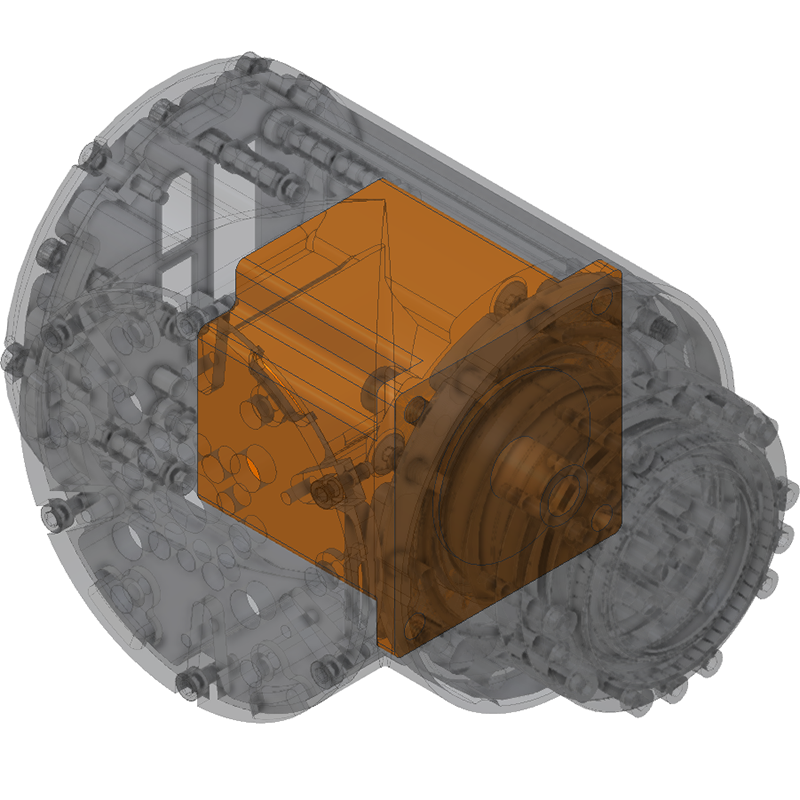
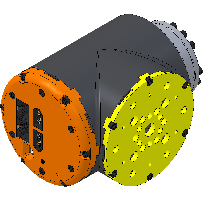 | The case of the Lynxmotion PRO Smart Servo is in three parts: the main body, the cap and the mounting plate. Each of these three parts is milled from aluminum and anodized black. | |
 | Main Body The main body is in the shape of a compact T, with the stepper motor located in the center. | |
 | Cap The cap supports the top and bottom PCB which make up the electronics inside the actuator. The bottom PCB must be located at the rear of the stepper motor in order to make use of the encoder. | |
 | Mounting Plate The mounting plate provides a convenient connection point onto which another actuator, clamp or bracket can be connected. As indicated above, it has the mounting pattern for the gearbox output for each of the three servo motors, as well as the clamp. | |
Connectors | ||
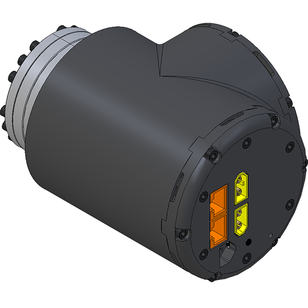 | | RJ45 - CAN Communication There are two RJ45 connectors which allow the servos to be daisy chained. Either connector can be used as the pinout is identical. More information about the pinout can be found on the LSS-P - Electrical page. |
| XT60 - Power The actuators are powered via ONE of the two XT60 connectors. The second XT60 is to provide power to the next actuator in the bus. Never feed an actuator with two sources of power. More information about the power requirements can be found on the LSS-P - Electrical page. | |
Gearing | ||
 | Each of the actuators use Strain Wave Gearing (a.k.a. "Harmonic Drive" which is a brand like "Kleenex" is associated with tissue paper). This allows for a high torque transfer and very high angular precision. Strain wave gearing is not meant to be back-driven. The gear ratios for each are:
| |
Stepper Motor | ||
 | Unlike many tabletop "Cobot" ("collaborative robot") robotic arms which use BLDC / frameless DC motors and measure the current needed for a motion, the LSS-P actuators use standard sized and industry proven bipolar stepper motors. These motors provide high torque at low speeds, but operate at a set current and therefore do not have a direct way of measuring the torque.
| |
Dimensions
| Lite / LSS-P-L1 | Standard / LSS-P-S1 | Mega / LSS-P-M1 |
|
|
|