LSS Mechanical
Page Contents
LSS Features
Spline | |
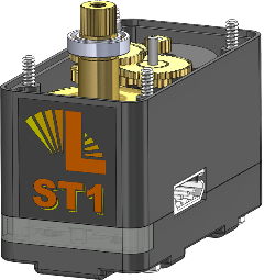
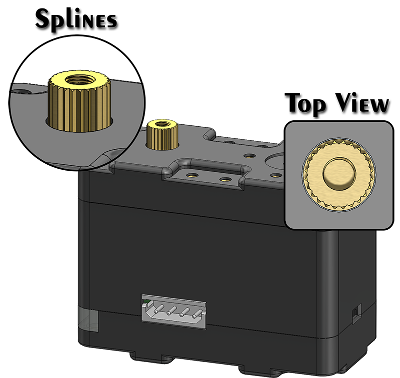 | The spline allows the driving horn to be connected to the output shaft so that it rotates with the shaft. The 24 tooth spline selected is used by other servo manufacturers (for example Hitec's HS-422 and HS-645MG RC servos) and as such there are a variety of accessories / horns which are compatible and can be installed on the servo. Alternatives to using the Lynxmotion driving horn include a wheel, a pulley or sprocket, a tubing connector, specific RC horns and more. Note that there are many different spline cross sections, and in order to ensure the a horn can fit onto the output shaft of the servo, it must have the matching / identical spline. Although the final gear which (located within the servo) which is connected to the output spline is supported by two radial ball bearings, the output spline is intended to withstand torque as opposed to radial or axial loads. Learn more about SES - Gearing & Horns |
Case | |
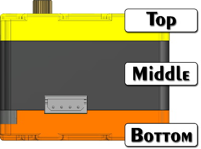 | The black plastic case which forms the body of the servo is made up of three sections: the top (highlighted in yellow), the bottom (opposite the driven horn and highlighted in orange), and the middle / center. All three case components are made of machined aluminum, anodized black. There are four screws located on the bottom case holding the servo together. Opening the servo without express permission from RobotShop / Lynxmotion staff will void the warranty. There are many threaded inserts in the top and bottom case, and their specifications and functionality are described below. |
LED Bar | |
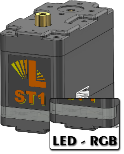 | The white opaque LED bar covers an internal RGB LED and has several functions:
|
Connector | |
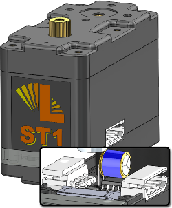 | There are two male four-pin 2.54mm (0.1") spaced MOLEX connectors located on either side of the servo. The connector is "keyed" to prevents mating except with a correctly oriented matching connector, and there is no locking mechanism. The pins are GND, VCC+, Rx (servo receive pin) and Tx (servo transmit pin). The order of the connector pins is reversed from one side of the servo to the other . In order to receive or send a command / signal only one side needs to be connected. The other connector need only be used when adding another servo to the chain. |
Button | |
 | The small button located at the rear of the servo is meant to allow the user to change the servo’s settings / configurations. The button is recessed so it is not pressed accidentally, nor is it meant to be used often, as the software interface allows for full control over these settings as well. Do not press the button too hard. |
Gearing | |
 | The internal gearing within the servo is located inside the top part of the case and has the effect of reducing the motor’s RPM while increasing the torque. The gear train is made up of a variety of metal spur gears. |
Motor | |
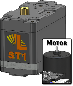 | The brushed DC motor is located within the central part of the case. The motor used in the high torque servo is coreless, while the motor used in the standard and high speed servos is cored. |
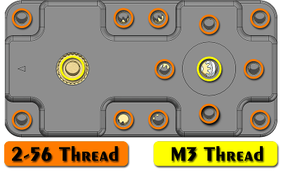
Threaded Inserts | |
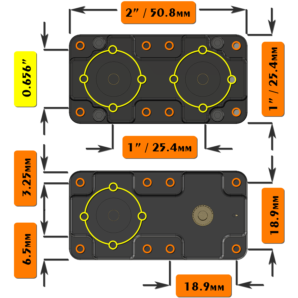
 | The top case of the servo includes 12x 2-56 threaded inserts plus one M3 threaded insert located at the center of the SES pattern as well as the M3 threaded spline shaft. |
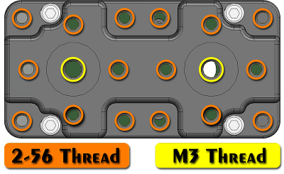 | The bottom case of the servo includes 16x 2-56 threaded inserts plus two M3 threaded inserts located at the center of the SES pattern. |
 | IMPORTANT NOTE: ONLY USE THE 2-56 x 14” SCREWS PROVIDED. LONGER SCREWS CAN AND WILL CAUSE DAMAGE TO THE SERVO. |
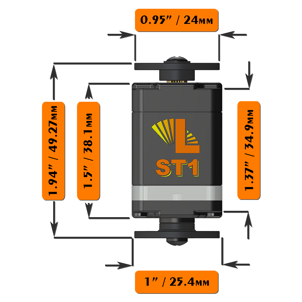
Dimensions
|
|