MES - Modular Frame
Table of Contents
The Multirotor Erector Set (MES) - Reconfigurable Frame is an all-in-one frame designed to allow the user to easily experiment with a variety of different multirotor designs, without having to invest in a variety of custom frames. The frame is based on the M.E.S. system which uses aluminum tubing clamps, G10 composite plates and carbon fiber tubing. A wide variety of different designs can be created using this single frame system and each can vary in terms of arm length, motor configurations, accessories and more.
Applications
- UAV / drone / multirotor education, development & experimentation
- Sensor experimentation
- Design & payload optimization
Features
- Reconfigurable center frame
- Mounting for one or two batteries
- Selection of different carbon fiber tube lengths
- Removable, quick release landing gear
- Variety of multi-purpose mounting mounts
- Quick release folding arms and removable landing gear
- Side mounted ESC for easy access
- Wiring within tubing
Assembly Guide
 | MES - Modular Frame KIT steps: MES - Modular Frame Parts |
What's Included
- G10 composite (non-conductive) parts for complete frame assembly
- Anodized (orange) aluminum tubing clamps
- Carbon fiber tubes
- Hardware (screws, standoffs, grommets, bearings, foam)
What's Needed
- Brushless DC (BLDC) motors (4 to 12 depending on design) and corresponding mounting screws
- Electronic Speed Controllers (ESCs) compatible with BLDC motors selected
- Flight controller (Lynxmotion Quadrino Nano suggested)
- Power Distribution (Lynxmotion Power Distribution Module suggested)
- Battery compatible with BLDC motors (one or two can be mounted)
- Remote Control (RC) system with minimum 4ch and receiver
- Optional: Gimbal; Video transmitter / receiver; Camera; Sensors;
Design Examples
The following designs are examples of what is possible with the MES system. These are all included in the assembly guide and allow you to become familiar with the system. Spare parts are included to allow you to create alternative designs, and additional hardware can be purchased separately.
| CAD Image | Title / Description |
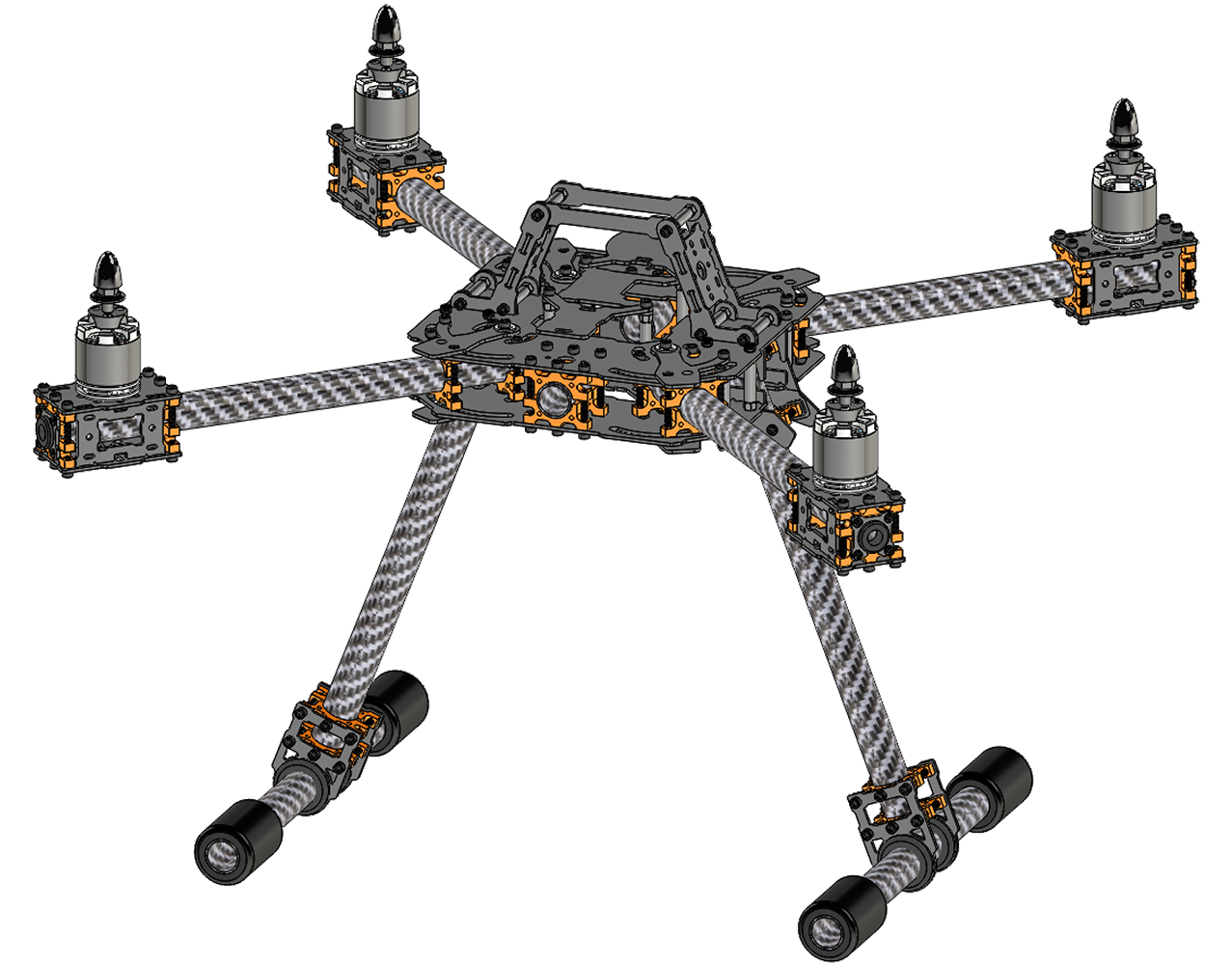
X4 Quadcopter The X4 quadcopter design incorporates folding arms and removable landing gear. There is a motor mounted to each of the four arms. Wiring is internal. | |
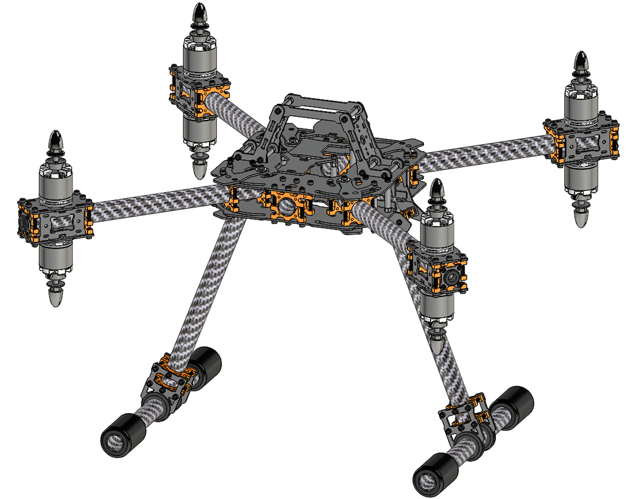
| X8 Quadcopter The X4 quadcopter design incorporates folding arms and removable landing gear. There is a motor mounted to both the top and the bottom of each of the four arms. Wiring is internal. |
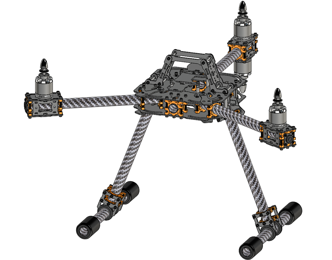
Y4 Tri Arms The Y4 design design incorporates folding arms and removable landing gear. There is one mounted to the front arms and two motors mounted to the center rear arm. | |
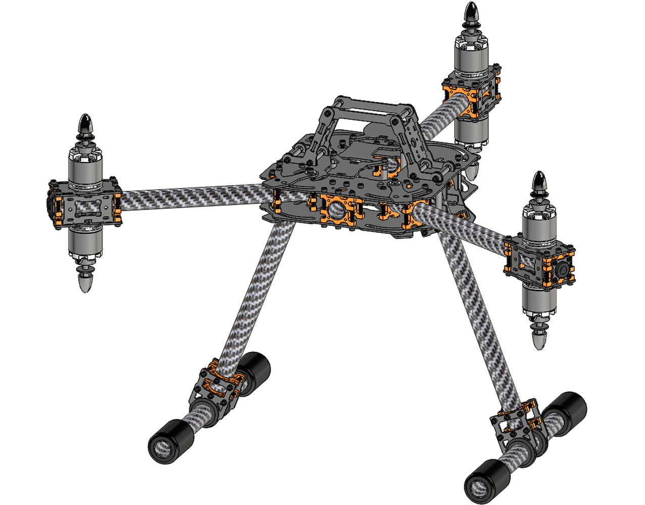
Y6 Tri Arms The Y6 design includes two folding arms, each with a motor, and a rear fixed arm with a motor mounted to the top and bottom of the arm. Wiring is internal. | |
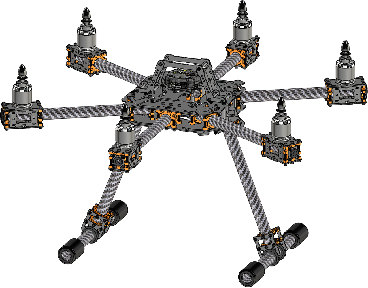
HEX 6 Hexacopter The H6 hexacopter design incorporates folding arms and removable landing gear. There is a motor mounted to each of the six arms,. Wiring is internal. | |
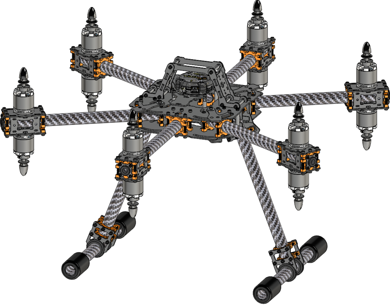
HEX 12 Hexacopter The H12 hexacopter design incorporates folding arms and removable landing gear. There is a motor mounted to both the top and bottom of each of the six arms. Wiring is internal. This design requires independent control of 12 motors, which is not supported by MultiWii / |
Design Guide
This section covers only the basics of how to select additional components to complete the MES frame.
Accessories
The types of accessories to connect to the frame are at the discretion of the designer. Components can be added above the frame or below, and a universal mounting plate is included. The length of the landing gear was selected in order to accommodate both a battery below the center frame as well as a standard two axis gimbal. For three axis gimbals, note that the distance between the bottom of the center frame and the ground is ____.
The Lynxmotion Servo Erector Set (SES) pattern has been incorporated into several positions on the frame. This pattern allows SES compatible hardware (brackets, C-channels and accessories) to be connected to the frame and used as universal mounting points. When mounting accessories, be check the center of gravity of the entire assembly and ensure it is at the very center of the drone. Should there be a weight imbalance, certain motors may need more power than others, and the flight characteristics may change significantly.
Battery
The MES frame supports using either one centrally mounted battery (below or above the main frame) or two batteries mounted on either the landing gear tubes or above the center plate. In a two battery configuration, we strongly recommend using identical batteries to ensure weight balance and uniform discharge. Note that both batteries should be fully charged before use, and your method of power distribution should support a two battery configuration. The battery is held in place by rubber foam and velcro straps, which supports a wide variety of different sizes. The battery's voltage should ideally match that of the BLDC motors selected, and the continuous discharge current rating ('C' rating) should be above the sum of the maximum current consumption of the motors used.
Motor, ESC, Propeller
In order to help determine the type and number of BLDC motors to use in a specific configuration, we propose following the steps below:
- Calculate the total weight of the multirotor drone based on the desired configuration by adding the weight of all known parts (frame, flight controller, power distribution)
- Add the total weight of any larger accessories such as a camera, gimbal system, video transmitter, heavier sensors etc. to the previous total.
- Estimate the weight of unknown parts (motors, battery) and add it to the total:
- Motor:
- Battery:
- The weight of the propellers, ESCs, receiver and lightweight sensors tend to have a minimal impact on the total.
- Multiply the total weight obtained by two*, and divide this new value by the number of motors to be used. This will give you an estimate of the maximum thrust needed per motor + propeller combination
- Select a motor + propeller combination which provides the thrust calculated in the previous step.
- Adjust the total weight calculated in the first step using the weight of the motors to re-calculate the total thrust needed per motor.
- Compare this new total to the maximum thrust which the motor can provide. If the motor's actual maximum thrust is less than around 90% of the thrust needed, find a new motor.
* Multiplying the total weight of the drone by a factor of two is an estimate to provide sufficient thrust needed for basic aerial maneuvers and acceleration. For more acrobatic flight, this multiplication factor should be higher.
Should you wish to experiment with a wide variety of different configurations using a single type of motor, ESC and propeller, the following specs are suggested. Note that :
- Motor thrust:
- ESC:
- Propeller:
- Battery:
Handheld Remote Control (RC)
The handheld remote control allows a human operator to control the drone remotely, and in the case of an autonomous drone, as a fail safe should the drone behave erratically. The minimum number of channels needed is four, with an additional channel often needed for each accessory / functionality. Many flight controllers require a full PWM range of 0.5ms to 2.5ms, which often requires that the remote control be configurable / programmable.


