03 - Wiring
| Radio Controlled (RC) / Bridged | |
Both motors on the left side are wired to one channel of the Sabertooth motor controller, and both motors on the right side are wired to the other. This ensures motors on the same side receive the same signal ("skid steering"). The Sabertooth's onboard BEC powers the RC receiver. Not Connected
| |
| |
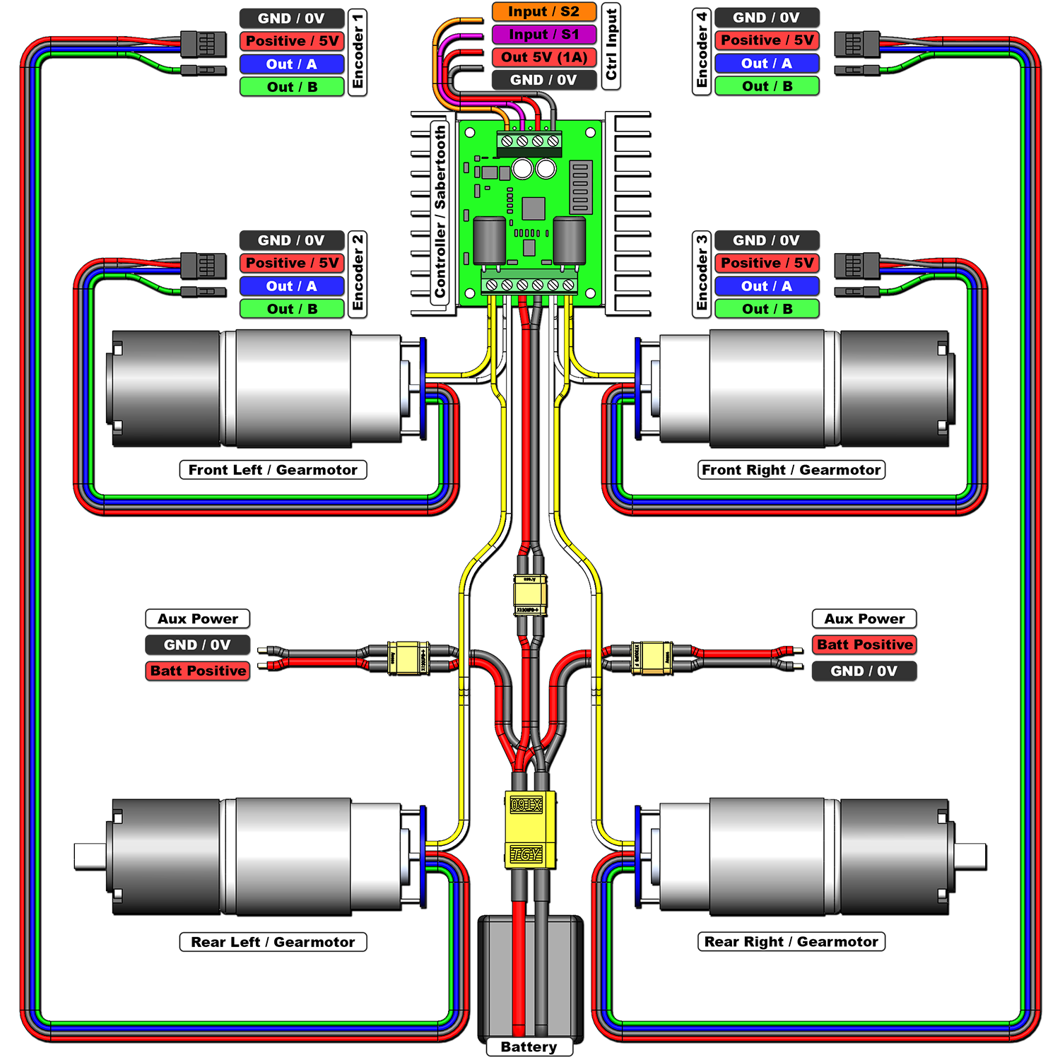
| Microcontroller / Bridged | |
Both motors on the left side are wired to one channel of the Sabertooth motor controller, while both motors on the right side are wired to the other. This ensures motors on the same side receive the same signal ("skid steering"). The Sabertooth's BEC can be used to power a microcontroller up to ~1A. If additional current is needed, consider using a spare XT30 split off from the main battery to power the microcontroller and disconnect the 5V (red) cable from the BEC. Optional Connections
| |
|
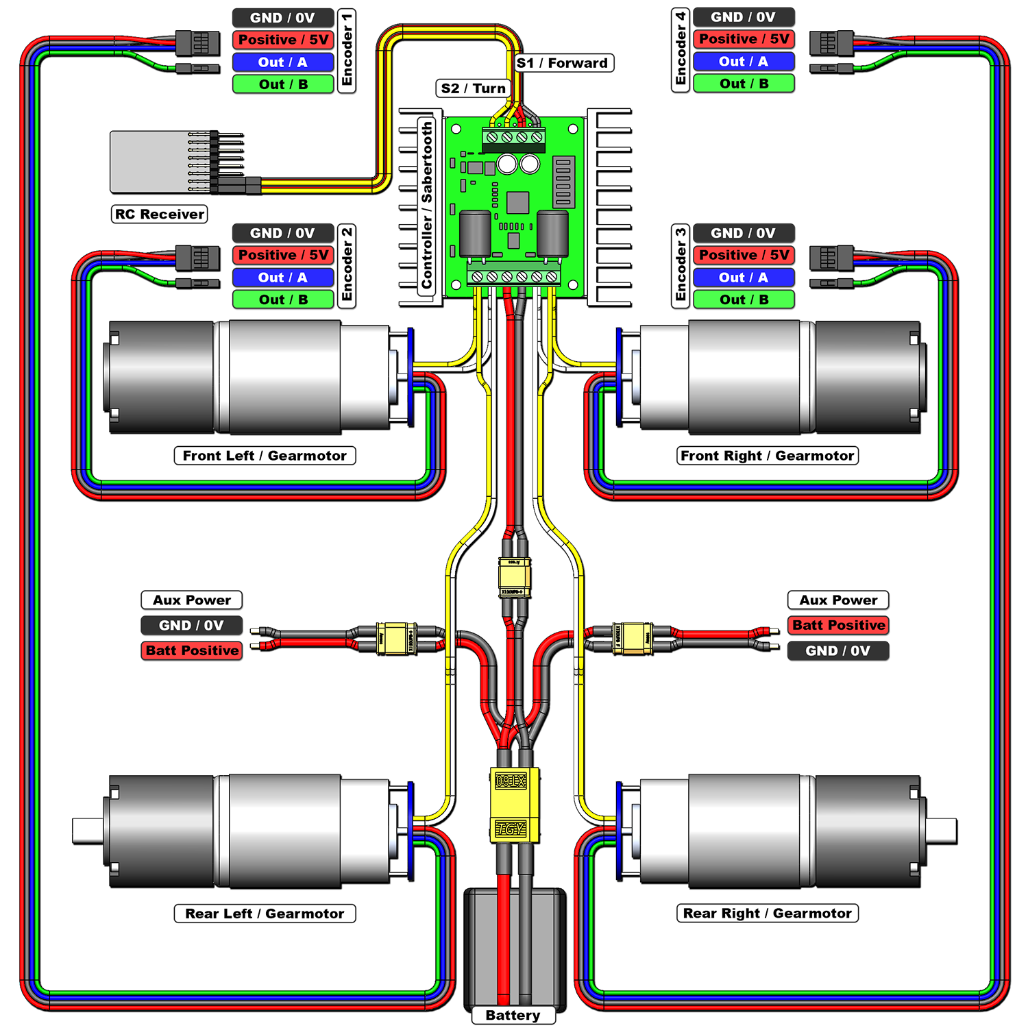
If the front and rear motors rotate in opposite directions however, the track which connects them will cause them to stall and burn very quickly! If you are at all uncertain, it is safest to remove the sprockets and test the motors. If they rotate in opposite directions, the wiring to the Sabertooth needs to be corrected.
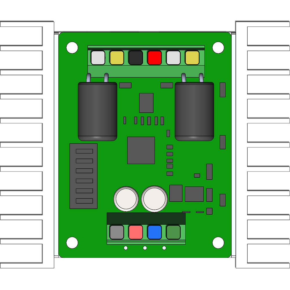
| Sabertooth 2 x 12A | ||
|  | Positive Input (6-24V / 30V Absolute Max) |
 | Negative Input / GND | |
 | M1A / M2A Outputs | |
 | M1B / M2B Outputs | |
 | Positive Output 5V (Max 1A) | |
 | Negative Output / GND | |
 | Signal 1 Input (S1) | |
 | Signal 2 Input (S2) | |
Details regarding the DIP switches can be found on the next page. Complete information available HERE | ||
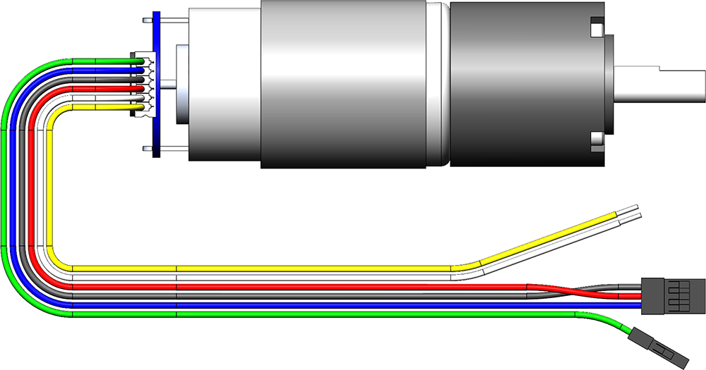
| Gear Motor (36GP 540-51-EN) | ||
| | Motor Positive |
| Motor Negative | |
| Encoder Negative / GND | |
| Encoder Positive (5V) | |
| Encoder Output 1 (Hall Effect) | |
| Encoder Output 2 (Hall Effect) | |
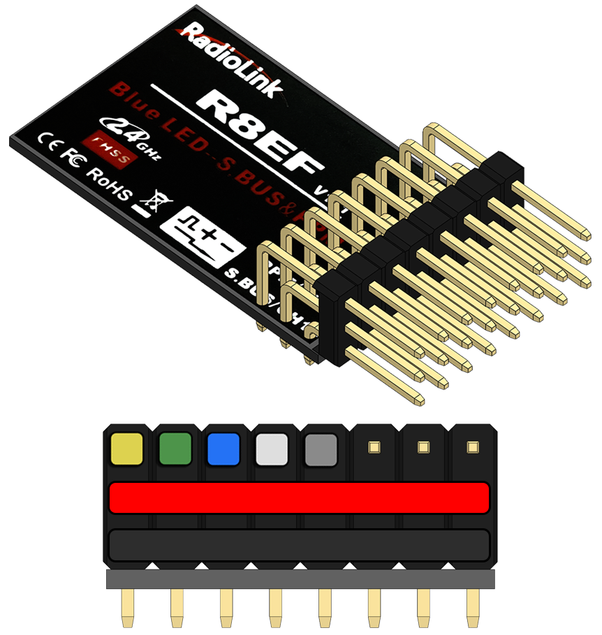
| RC Receiver (RadioLink R8EF) | ||
| | Positive Input & Distribution (5-6V) |
| Negative Input / GND & Distribution | |
| Channel #1 (SBUS Optional) | |
| Channel #2 (PPM Optional) | |
| Channel #3 | |
| Channel #4 | |
| Channel #5 | |