
The Complete 2DoF Hexapod Tutorial
The Complete 2DOF Hexapod Tutorial
Updated September 30, 2010
This tutorial follows the 2DOF Hexapod assembly guide. Make sure all servos and other connections are set up as detailed there.
Required Hardware
Any Lynxmotion 2 DOF Hexapod, SSC-32, Bot Board / BASIC Atom Pro 28, PS2 Cable, PS2 Wireless Controller (not included in combo kit), Sharp GP2D12 Sensor (optional)
Required Software
LynxTerm (free download) | Basic Micro Studio ver 2.0.0.0
Basic Atom Pro Hexapod Programs:
h2prog01.zip PS2 |
h2prog02.zip PS2 |
h2prog03.zip PS2 |
h2prog04.zip Autonomous
Resources
Wiring Schematic (2dofsch2.gif)
Goal
Install, program, and test the electronics to operate a Hexapod 2 remotely from a Lynxmotion wireless controller or autonomously using sensors.
Connect the serial data cable to the PC's serial port (recognized by 9 pins that stick out). Connect the other end to the SSC-32's DB9 port.
Note: if your computer does not have a native serial port, you can use a high quality USB to Serial adapter such as one made by FTDI. If using an FTDI adapter, install the VCP (Virtual Com Port) driver and change the "latency" property to its minimum.
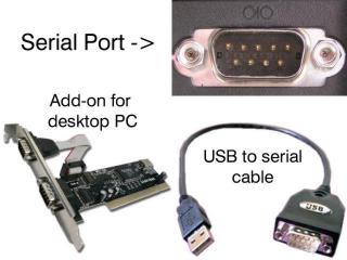 Figure 1.
Install and run LynxTerm on your PC. Plug in the 9VDC battery and notice the green LED light up on the SSC-32. Choose the COM port from the drop down menu in the upper left corner.
Click in the black box, type "ver" and press Enter. If everything is working correctly, you should receive a response such as "SSC32-2.03XE".
Note: the LED on the SSC-32 is a status indicator, not a power indicator. It lights up on power up, turns off after receiving a serial command, then blinks when it receives data. The LED on the Bot Board II is a simple power indicator.
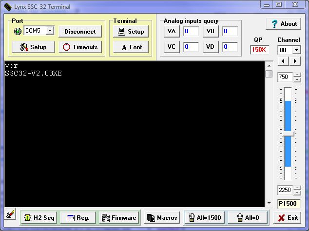 Figure 2. (click to enlarge)
Place the robot on top of a CD spindle or similar object to support the body and lift the legs off the ground. Make sure the 6V battery is connected to the wiring harness and flip the power switch to ON.
Click the "All=1500" button at the bottom of the program and the legs should move to a centered position. If the robot was constructed properly, the legs will be horizontal and perpendicular to the body. If the legs are more than 15° off, remove the output horn, rotate it, and reinstall it. The next step is to align the servos in software.
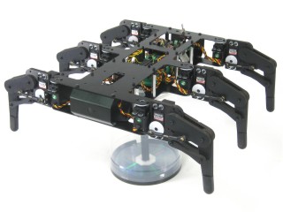 Figure 3.
Click on the H2 Sequencer button in the lower left corner. Use the Offset tool under Servo Quick Test. Click "Read" to load any previous offset settings. Select each servo on the Hexapod diagram and adjust the offset slider to fine-tune the leg alignment. Do this for all twelve servos. When completed, click "Write" to save your offsets to the SSC-32 EEPROM.
Refer to Figures 4-2 and 4-3 for how each servo should be aligned.
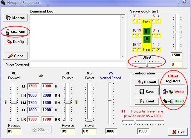 Figure 4-1. (click to enlarge)
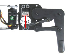 Figure 4-2.
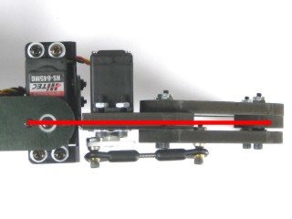 Figure 4-3.
Schematic. Double check your connections. Red wires to positive (+), black wires to negative (−). Note: your PS2 cable may not match Schematic 1 — refer to Schematic 2 for accurate connection information.
Schematic 1.
Schematic 2.
Install and run the BASIC Micro Studio to allow programming the chip. Refer to this tutorial for assistance using the BASIC Micro Studio program.
| Available Programs | |
| h2prog01.zip | Default program |
| h2prog02.zip | Tank mode and single joystick mode |
| h2prog03.zip | Single joystick mode and pan-and-tilt on left joystick |
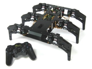 Figure 5.
Control the direction of walking with the right joystick. Left and Right on the D-Pad adjusts speed in 5% increments (up to 200%). The joystick positions will allow a max of 100% XS speed initially.
Both modes offer additional control of leg trajectory. Pressing △, O (default), X, or □ changes how the foot is lifted during the walking gait.
If the robot is driven toward an obstacle, the forward joystick position is ignored after a threshold is reached, but you can still reverse direction. The controller will also vibrate proportionally to obstacle distance. The Sharp sensor can be enabled/disabled with the Start button.
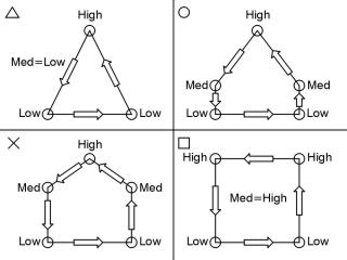 Figure 6.
PS2 Controls — Right-Joystick Mode (h2prog01.zip)
| L Joy U | Tilt Servo up | R Joy U | Forward |
| L Joy D | Tilt Servo down | R Joy D | Backward |
| L Joy L | Pan Servo left | R Joy L | Left |
| L Joy R | Pan Servo right | R Joy R | Right |
| △ | See Figure 8 | □ | See Figure 8 |
| X | See Figure 8 | O | See Figure 8 |
| D-Pad L | Speed Limit Down | D-Pad R | Speed Limit Up |
| Start | Disable/Enable Crash Monitor |
PS2 Controls — Right Joystick Mode (h2prog03.zip)
| L Joy U | Tilt Servo up | R Joy U | Forward |
| L Joy D | Tilt Servo down | R Joy D | Backward |
| L Joy L | Pan Servo left | R Joy L | Left |
| L Joy R | Pan Servo right | R Joy R | Right |
| All other commands | See Tank Mode table below | ||
PS2 Controls — Tank Mode or Right Joystick Mode (h2prog02.zip)
| L Joy U | Left Side Forward (N/A) | R Joy U | Right Side Forward (Forward) |
| L Joy D | Left Side Backward (N/A) | R Joy D | Right Side Backward (Backward) |
| L Joy L/R | N/A | R Joy L/R | N/A (Left/Right) |
| L1 | Raise body height | R1 | Increase leg lift |
| L2 | Lower body height | R2 | Decrease leg lift |
| L3 | N/A | R3 | Switch control mode |
| D-Pad U | Raise body height | △ | See Figure 8 |
| D-Pad D | Lower body height | X | See Figure 8 |
| D-Pad L | Speed Limit Down | □ | See Figure 8 |
| D-Pad R | Speed Limit Up | O | See Figure 8 |
| Start | Disable/Enable Crash Monitor | Select | N/A |
The autonomous program requires three Sharp GP2D12 sensors connected as follows:
- A to D channel 0: front left side, facing right
- A to D channel 1: front right side, facing left
- A to D channel 2: rear, facing behind the robot
The exact angle of the sensors isn't critical, but will affect the robot's behavior. Experimentation is encouraged.
| Autonomous Program | |
| h2prog04.zip | Autonomous using two Sharp GP2D12 sensors and one on the rear |
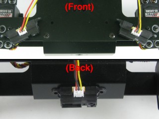 Figure 7.
The Hexapod Sequencer can be used to test the hexapod without a microcontroller. Connect the SSC-32 to the serial port as if aligning the servos, then follow along.
The L* and R* textboxes control the positions the legs move to in the sequence. Fine-tune these values using the Servo Quick Test position slider.
| Tripod Leg Movement Sequence | |||
| LF | Left Front Horiz | RF | Right Front Horiz |
| LH | Left High Vertical | RH | Right High Vertical |
| LM | Left Middle Vertical | RM | Right Mid Vertical |
| LL | Left Low Vertical | RL | Right Low Vertical |
| LR | Left Rear Horiz | RR | Right Rear Horiz |
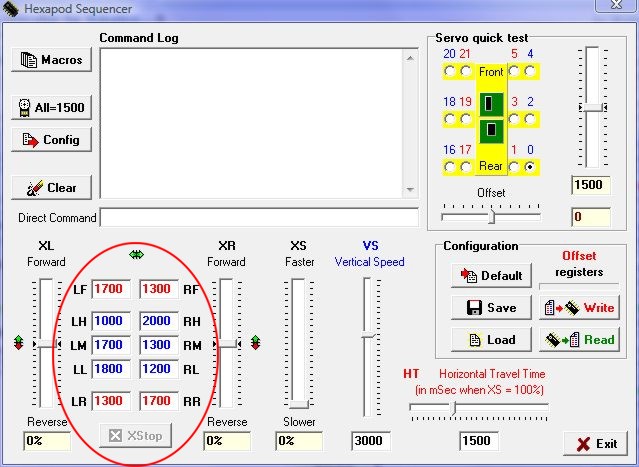 Figure 8. (click to enlarge)
Adjust the XL and XR sliders to 100%. Note that HT=1500uS (1.5 seconds). Set the XS slider to ~50% and notice the stride takes 3 seconds. Adjust HT to 1000 and the stride now takes 2 seconds.
You have complete control over all aspects of the tripod gait. Adjust either XL or XR lower to do gradual turns. Setting XL and XR to opposite directions causes the robot to turn in place. Reverse values cause the robot to walk backwards.
Moving a slider is the same as sending the command from a microcontroller — for example, moving XS to 50% is the same as sending "XS50". The robot will continue to walk until it receives XS = 0.
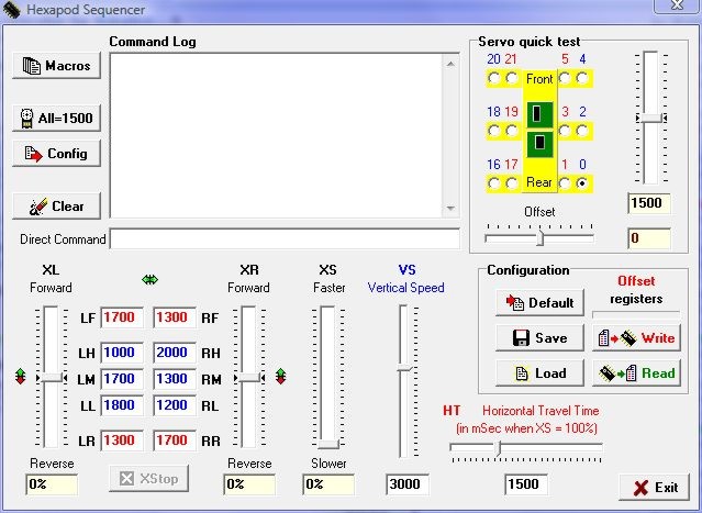 Figure 9. (click to enlarge)
The following program will set up and initiate walking on the robot. To change speed and direction, just alter the XL, XR, XS values. The robot will immediately begin walking in the speed and direction commanded.