The A-POD Body Assembly Guide.
Updated
11/04/2011
|
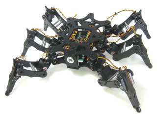
Image of body. |
| |
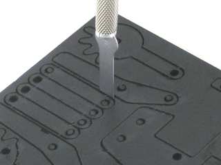
Removing the parts from the panel
The PVC parts need to be carefully cut out of the panel. A thin, flat blade exacto knife will be very helpful when removing the parts. Simply cut through the tabs to remove the parts. |
Parts in the kit. |
| |
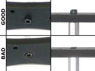
IMPORTANT!
DO NOT overtighten screws on the PVC parts! The PVC will compress and will become weaker as a result! |
Example image. |
|
Step 1.
Attach a Multi-purpose bracket to the top body panel using four 2-56 x .375" screws and nuts as shown. This will be on the inside of the chassis, so attach it to the "bad" side of the material.
| 4 x |
|
 |
|
|
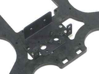
Figure 1. |
|
|
Step 2.
Attach a servo to the bracket using the 3mm attachment kits. You will need to put the screws in reverse of the normal for this. Don't tighten it down completely yet.
| 4 x |
|
 |
|
|
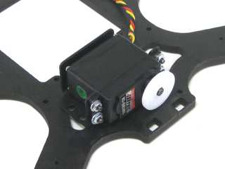
Figure 2.
|
| |
Step 3.
Drill out the tapped holes on a metal servo horn with a .125" bit. Connect the modified servo horn to a .5" spacer with four 2-56 x .25" screws.
| 4 x |
|
 |
|
|
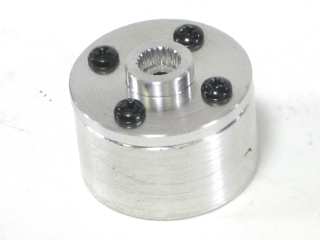
Figure 3.
|
| |
Step 4.
Remove the nylon servo horn from the servo and slide the support into place. The large hole should be in front of the servo shaft. |
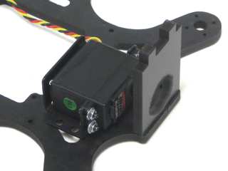
Figure 4. |
|
Step
5.
Attach the metal servo horn and standoff to the servo horn using the same screw that was holding the nylon one in place. Make sure that the servo can rotate freely, and then tighten down the screws holding it in place. |
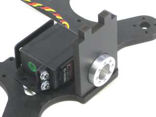
Figure 5.
|
| |
Step 6.
Attach eight hex standoffs to the top panel using 4-40 x .375" hex screws.
| 4 x |
|
 |
|
|
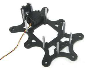
Figure 6. |
|
Step
7.
Using four 4-40 x .375" hex socket head screws, attach four 0.375" nylon hex spacers to the bottom panel as shown. Note that these should be on the outside of the robot, so they should be placed on the "good" side of the material.
| 4 x |
4 x |
|
 |
|
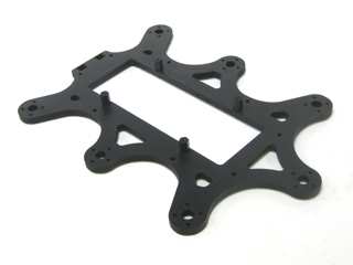
Figure 7.
|
|
Step
8.
Attach the bottom panel to the top using eight 4-40 x .375" hex screws as shown.
| 8 x |
|
|
|
|
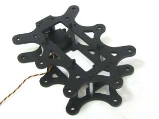
Figure 8.
|
| |
Step 9.
The body kit comes with a battery holder. You can attach a battery directly to it using two zip ties as shown. This will allow easy removal of the battery for charging.
|
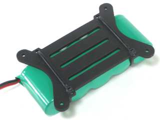
Figure 9. |
|
Step 10.
The battery holder is then attached on the underside of the robot using four 4-40 x .25" hex screws.
| 4 x |
|
 |
|
|
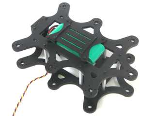
Figure 10. |
|
Step 11.
Using four 4-40 x 0.25" hex socket head screws, attach the 0.75" hex spacers to the board as shown.
The SSC-32 should be configured for 115.2 kbaud and DB9 communication, with the VS2=VS1 jumper installed. Remove the VL=VS jumper. Consult the SSC-32 manual if needed. Attach the wiring harness to VS1. Connect 8" of 24awg wire (not included) AND the 9v battery clip to VL; this will provide power for the electronics. Make sure that the red wires go to (+) and the black wires go to (-).
| 4 x |
4 x |
|
 |
|
.jpg)
Figure 11. |
| |
Step 12.
Slide the SSC-32 into place and secure it using four 4-40 x .375" hex screws. Attach the power switch to one of the outer mounting holes. Using one of the inner ones will block the DB9 cable from being able to be plugged into the SSC-32.
| 4 x |
|
|
|
|
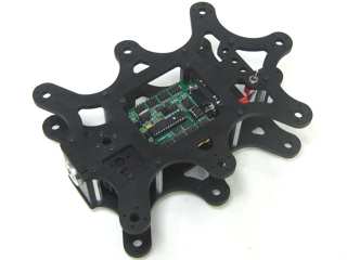
Figure 12. |
| |
Step 13.
Attach all six legs using four 2-56 x .375" screws each.
| 24 x |
|
|
|
|
Figure 13. |
| |
