
A-Pod 3DoF Bot Board II / BASIC Atom Pro Tutorial
A-Pod Bot Board II / BASIC Atom Pro Tutorial
Updated August 10, 2010. Phoenix code v2.0
Safety first! Wear eye protection and never touch a powered robot!
Required Software
Basic Micro Studio | Basic Atom Pro program
Place the robot on top of a CD spindle or similar to hold the legs off the ground.
Download and install the latest version of LynxTerm.
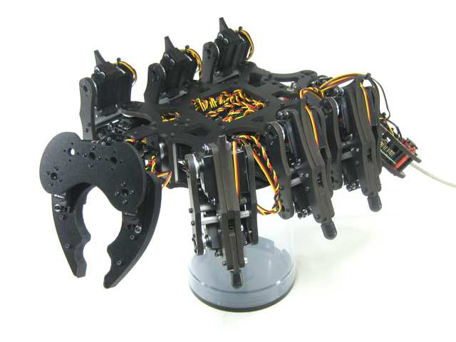 Figure 1.
Connect the SSC-32 to the PC's serial port (recognized by the 9 pins that stick out). Apply power — the green LED should light and stay on until it receives a valid serial command. Run the LynxTerm program.
To test basic communications, type "ver" into the terminal and press Enter. You should see the proper firmware version returned.
Please consult the serial troubleshooting guide if you have difficulties.
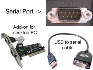 Figure 2.
Download the 2-07EGP_A1A.abl firmware or higher. Make sure the baud rate is set to 115.2k before attempting to update. Refer to the manual for baud rate information.
Click "Firmware" along the bottom of the LynxTerm screen. Click "Open" and browse to the firmware file. Make sure the SSC-32 is powered, and click "Begin Update".
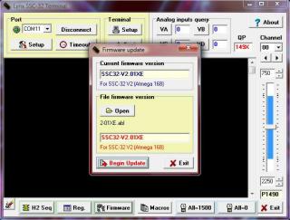 Figure 3.
When the firmware has been successfully updated, click "Ok" then "Exit".
Do another "ver" test: type "ver" into the terminal then press Enter. You should see the new firmware version returned.
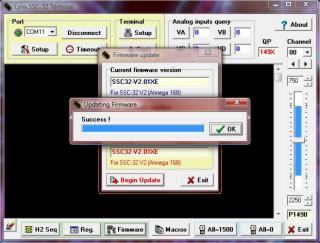 Figure 4.
Place the robot in a position as close to neutral as possible. Click "All=1500" in the bottom right portion of the screen. The robot should go to and hold the neutral position. If the joints are off by more than 15°, remove the center screw from the round servo horn, pull it off, rotate until aligned, then reattach.
Caution! You are about to power up the servos. When this is done, immediately make sure all moving parts are not tangled or beyond their range of motion. This robot has long appendages — you must periodically allow the servos to cool if left on for more than 5 minutes. Monitor the vertical servos, especially the head and tail, to prevent overheating during calibration.
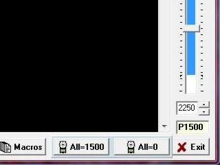 Figure 5.
From the main screen, click "Reg" to open the Registers page. Click "Default" to initialize default values.
Do the most accurate alignment as possible! The robot can only operate as well as it is aligned. A poorly aligned robot will walk poorly.
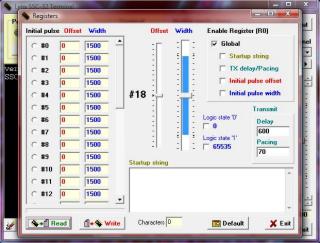 Figure 6.
Refer to this servo channel number guide for the following configuration steps.
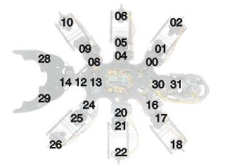
Servo Channel Numbering.
Adjust the robot's horizontal hip servos. Select servo #04, then adjust the "Offset" slider until the leg is perpendicular to the robot's chassis as shown.
Do this for servos #04 and #20.
Note: the mouse's scrollwheel or keyboard arrow keys can be used for fine adjustments.
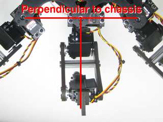 Figure 7.
Adjust the robot's remaining horizontal hip servos. Select servo #00, then adjust the "Offset" slider until the tibia is at a 45° angle from the robot's chassis as shown.
Do this for servos #00, 08, 16, 24.
Note: the mouse's scrollwheel or keyboard arrow keys can be used for fine adjustments.
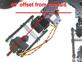 Figure 8.
Adjust the robot's vertical hip servos. Select servo #1, then adjust the "Offset" slider until the robot's femur is parallel to the ground as shown.
Do this for servos #01, 05, 09, 17, 21, 25.
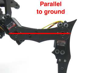 Figure 9.
Adjust the robot's knee servos. Select servo #2, then adjust the "Offset" slider until the tip of the robot's foot is directly underneath the knee servo pivot point — from the pivot point to the tip of the foot should be perpendicular to the ground as shown.
Do this for servos #02, 06, 10, 18, 22, 26.
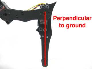 Figure 10.
Adjust the robot's mandible servos. Adjust #13 and #14 until the mandibles are level with the ground, both from the front and side.
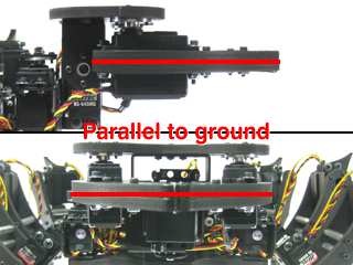 Figure 11.
Adjust servo #12 until the mandibles are inline with the chassis. Adjust the two gripper servos (#28 and #29) so that they just barely touch each other, as shown. It is important that the gripper servos are not straining against each other.
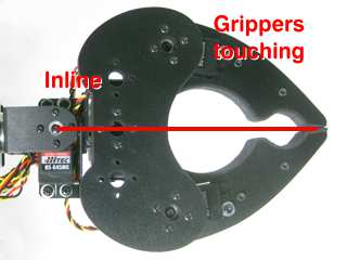 Figure 12.
Adjust #30 until the abdomen is inline with the chassis. Adjust #31 until the abdomen is parallel to the ground.
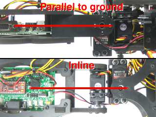 Figure 13.
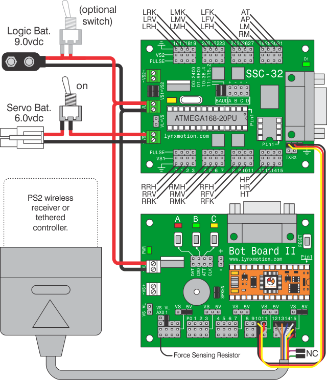
Modify a 12" servo extender cable by removing the header pins so you have two female ends. Use an exacto knife to gently pry the tab up to pull the red wire free on one end. Cover the exposed connector with heat shrink to avoid accidental shorts.
Remove the TX and RX jumpers from the lower-right corner of the SSC-32 and plug the unmodified end of the cable in: yellow on TX, red on RX, black on ground.
Plug in extra lengths of 18-24AWG wires to VL on the SSC-32 with the 9VDC battery clip — these will power the Bot Board II.
See Tables 15-2 through 15-4 and the schematic below for connection information.
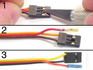 Figure 14.
Plug the modified servo cable end into the Bot Board II: yellow and black wires on pin 10 with black toward the outside, red wire on pin 11 toward the center.
Plug in the PS2 cable as shown in Figure 15-1. Plug in the power wires from the SSC-32 to VL.
Note: refer only to Figure 15-1 for connection information — cable colors in the picture may be outdated. A complete listing of possible colors is available here.
Install the BASIC Atom Pro as shown in the orientation diagram.
 Figure 15-1.
 Atom Pro Orientation.
SSC-32 Connection Information (Table 15-2)
| What | Where |
|---|---|
| Jumper installed | VS1=VS2 |
| Jumper installed | 38.4 Baud Rate |
| Unmodified Servo Cable End | TX / RX / GND (Black on GND) |
| 9VDC Battery Clip | VL |
| Power Wires | VL to BBII's VL |
| Battery Wiring Harness | VS1 |
Bot Board II Connection Information (Table 15-3)
| What | Where |
|---|---|
| Power Wires | SSC-32's VL to VL |
| Modified Cable — Black & Yellow | Pin 10, Black toward outside |
| Modified Cable — Red wire | Pin 11, toward center |
| Power jumper for I/O group 12-15 | 5VDC |
| PS2 Cable | I/O Group 12-15 |
Servo Channels and Schematic Label Explanations (Table 15-4)
| Label / Ch. | Function | Label / Ch. | Function | Label / Ch. | Function |
|---|---|---|---|---|---|
| RRH / 00 | Right Rear Horizontal Hip | LRH / 16 | Left Rear Horizontal Hip | RM / 28 | Right Mandible |
| RRV / 01 | Right Rear Vertical Hip | LRV / 17 | Left Rear Vertical Hip | LM / 29 | Left Mandible |
| RRK / 02 | Right Rear Knee | LRK / 18 | Left Rear Knee | AP / 30 | Abdomen Pan |
| RMH / 04 | Right Middle Horizontal Hip | LMH / 20 | Left Middle Horizontal Hip | AT / 31 | Abdomen Tilt |
| RMV / 05 | Right Middle Vertical Hip | LMV / 21 | Left Middle Vertical Hip | HP / 12 | Mandible Pan |
| RMK / 06 | Right Middle Knee | LMK / 22 | Left Middle Knee | HR / 13 | Mandible Rotate |
| RFH / 08 | Right Front Horizontal Hip | LFH / 24 | Left Front Horizontal Hip | HT / 14 | Mandible Tilt |
| RFV / 09 | Right Front Vertical Hip | LFV / 25 | Left Front Vertical Hip | ||
| RFK / 10 | Right Front Knee | LFK / 26 | Left Front Knee | ||
Schematic.
Download Basic Micro Studio. Install and run the IDE to allow programming the chip.
Download the .zip file and unzip it. Open the .prj file in Studio (File → Open → *.prj) and verify that the files in the Workspace are in the order shown in Table 16. Install the PS2 controller receiver, make sure your controller is on, then apply power. Program the Atom Pro.
If all is well, you will hear a beep after power up. Press Start and the legs should snap to position. If you properly calibrated the servo offsets, the legs should be perfectly aligned.
Note: the software switches the controller to analog mode, but some controllers may need to be put into analog mode manually. Continuous beeping means the PS2 controller is not connected or not functioning. You can press Reset on the Bot Board II, or test the controller with a PlayStation 2.
A-Pod BASIC Atom Pro Program (Table 16)
| Phoenix: apodps2.zip | |
|---|---|
|
apod_ps2.prj Phoenix_Config_3DOFAPod.bas Phoenix_Control_ps2.bas Phoenix_Core.bas Phoenix_Driver_SSC-32.bas |
The default is Walking mode 1. Use the Left joystick to move without turning (translation), and the Right joystick to rotate. D-Pad Up/Down adjusts body height. Triangle swaps between walking stance and resting position.
Circle and X trigger special "body moves" modes where the joysticks and some buttons change function — see Table 17 below for details.
| Button | Function |
|---|---|
| Common Controls | |
| Start | Turn robot on/off |
| R3 | Toggle full/half head rotation range |
| L1 | Open Mandibles |
| L2 | Close Mandibles |
| L2 + D-Pad Left | Decrease gripper torque |
| L2 + D-Pad Right | Increase gripper torque |
| O Circle | Toggle Rotate mode |
| X Cross | Toggle Shift mode |
| □ Square | Toggle Balance mode |
| △ Triangle | Switch between 35mm height and ground |
| D-Pad Up | Body up 10mm |
| D-Pad Down | Body down 10mm |
| D-Pad Left | Decrease speed by 50mS |
| D-Pad Right | Increase speed by 50mS |
| Walk Mode Controls (default) | |
| Select | Change gaits |
| Left Joystick | Mode 1: Walk/strafe | Mode 2: Disabled |
| Right Joystick | Mode 1: Rotate | Mode 2: Walk/rotate |
| R1 | Toggle double gait travel height |
| R2 | Toggle double gait travel length |
| Button | Function |
|---|---|
| Shift Mode Controls | |
| L1 | Turn Shift mode off |
| Left Joystick | Shift body X/Z |
| Right Joystick | Shift and rotate body Y |
| Rotate Mode Controls | |
| O Circle | Turn Rotate mode off |
| Left Joystick | Rotate Y / Translate Z |
| Right Joystick | Rotate Z/X |
| Select | Cycle rotate function (Head tracking / fixed head / head only) |
| R1 | Move center of rotation to head (when held) |
| R2 | Move center of rotation to tail (when held) |
| L3 | Reset body rotations |
PS2 Controls — Table 17.