The A-POD Tail Assembly Guide.
Updated
11/04/2011
|
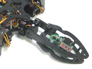
Image of attached tail. |
| |
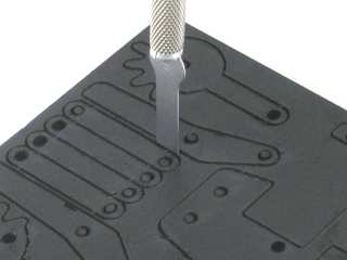
| Removing the parts from the panel
The PVC parts need to be carefully cut out of the panel. A thin, flat blade exacto knife will be very helpful when removing the parts. Simply cut through the tabs to remove the parts. |
Parts in the kit. |
| |
IMPORTANT!
DO NOT overtighten screws on the PVC parts! The PVC will compress and will become weaker as a result! |
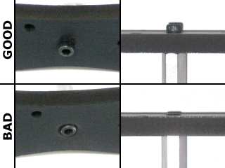
Example image. |
| |
Preparation.
Remove the nylon servo horn from each servo and replace them with a metal servo horn. Be sure to keep it in the same orientation. |
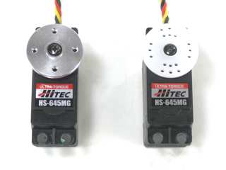
Example image. |
|
Step 1.
Attach a ball bearing to a Multi-purpose bracket as shown. See the diagram below for detailed information. Make two of these.
Figure 1-1.
|
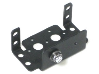
Figure 1. |
|
|
Step 2.
Attach the two brackets together as shown using two 2-56 x .25" screws and two 2-56 nuts.
| 2 x |
2 x |
 |
 |
|
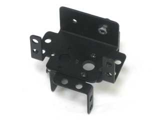
Figure 2.
|
| |
Step 3.
Attach four 1.0" hex spacers to the "bad" side of the top panel with four 4-40 x .375" screws.
| 4 x |
4 x |
 |
 |
|
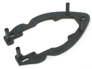
Figure 3.
|
| |
Step 4.
Using four 4-40 x .250" hex socket head screws, attach four 0.75" hex spacers to the Bot Board II as shown. Insert the Basic Atom Pro 28 chip into the socket.
| 4 x |
4 x |
 |
 |
|
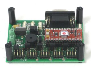
Figure 4. |
|
Step
5.
Attach the Bot Board II to the top panel of the tail using four 4-40 x .375" screws.
| 4 x |
|
|
|
|
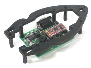
Figure 5.
|
| |
Step 6.
Slide the two "T" shaped PVC pieces into the slots as shown. Attach the bottom panel using four 4-40 x .375" hex screws.
| 4 x |
|
|
|
|
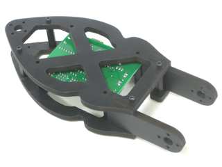
Figure 6. |
|
Step
7.
Slide the bracket assembly into place as shown. |
.jpg)
Figure 7.
|
|
Step
8.
Slide a HS-645MG servo into the bracket and secure it using 3mm hardware, as shown. Attach it to the PVC with four 2-56 x .375" screws.
| 4 x |
4 x |
 |
 |
|
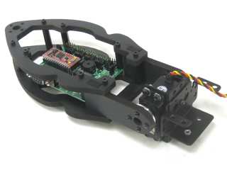
Figure 8.
|
| |
Step 9.
Slide the tail assembly in place in the rear of the chassis.
|
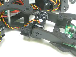
Figure 9. |
|
Step 10.
Attach a HS-645MG of the robot using 3mm screws, washers and nuts. Connect the servo horn to the chassis using four 2-56 x .375" screws.
| 4 x |
4 x |
|
|
|
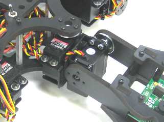
Figure 10. |
|
| |
