Hexapod Foot Sensor Assembly Guide
Hexapod Foot Sensor Assembly Guide
By James Frye. Updated February 14, 2008
This tutorial guides you through building and setting up a Hexapod Foot Sensor using a Force Sensing Resistor (FSR).
Kit Contents & Required Materials
The kit includes two FSRs, hexapod foot caps, rubber bumpers, and hubs. You will need to provide: electrical tape, 24–28 AWG hookup wire, heat shrink, solder, and a nylon wire tie.
Note: This kit is compatible with the AH3-R and 3DOFA legs (BRU/BLK).
Solder some 24 gauge or lighter wires onto the force sensors as shown. Cover the connections with heat shrink.
Note: the wires will need enough slack to not bind the legs while the robot is walking. Be generous with the wire length at first — you can always trim after everything's in place.
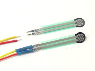 Figure 1.
Attach the tubing hub to the tubing using a button head screw as shown.
Note: if your hubs include additional 4-40 socket head cap screws, they are not needed in this assembly.
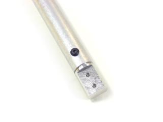 Figure 2.
Cover the side of the tube opposite the screw head with electrical tape. This will prevent the sensor terminals from shorting to the tube.
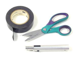 Figure 3.
Use an exacto knife to carefully peel away the clear plastic piece covering the black adhesive. Be very careful — if not done carefully the sensor can be damaged!
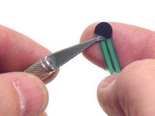 Figure 4.
Stick the adhesive side of the sensor to the end of the leg as shown, then carefully bend the wires to lay along the leg. Do not bend the sensor tail too sharply! Secure the sensor tail and wires to the leg with electrical tape.
Note: the sensor should be centered on the flat of the aluminum hub.
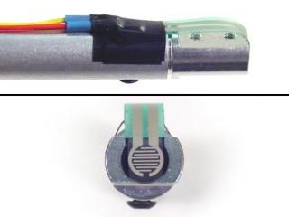 Figure 5.
Peel an adhesive-coated bumper off of the paper and stick it firmly on the end of the leg as shown.
Note: this should be centered precisely on top of the FSR. Clear rubber bumpers are included to make alignment easier.
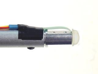 Figure 6.
Attach a nylon wire tie to the wires. Connect an ohm meter to the FSR wires. Gently slide the rubber foot over the sensor and tip of the foot. Push it on until the meter reads some resistance, then carefully work the rubber end cap back in the opposite direction just until the meter reads open.
If you are unable to get the meter to read open (infinite resistance), you may need to adjust the wire tie or the bend on the sensor from Step 5. After proper setup, the sensor should read open until it makes contact with the ground.
On a moving robot, the rubber end cap holds the sensor in place even with significant lateral loading, and the sensor returns to open even after being under load for a long time.
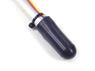 Figure 7.
The simplest way to use the FSR is with a 10k pull-up resistor. Two wiring setups are shown in Figure 8.
Setup "A" produces the response illustrated by the red line in the Sensor Output Chart. Setup "B" produces the response illustrated by the blue line.
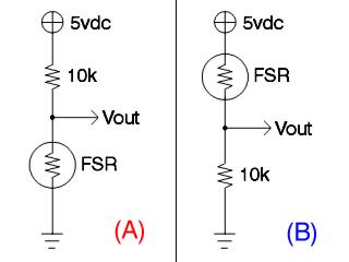 Figure 8.
Sensor Output Chart. Refer to the chart below for expected pressure vs. voltage values.