
Arm Gripper FSR Assembly Guide
Arm Gripper FSR Assembly Guide
By James Frye — Updated June 10, 2009
This tutorial guides you through the process of building and setting up your arm gripper sensor. The sensor used is a Force Sensing Resistor (FSR).
The FSR-01 kit includes one FSR and a rubber bumper. You will also need to provide: 24" Servo Extender Cable (SEA-03), electrical tape, heat shrink, solder, and a nylon wire tie.
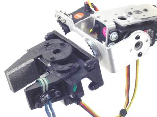
Sensor on gripper.
Use an exacto knife to carefully peel away the clear plastic piece covering the black adhesive. Be very careful — if not done carefully the sensor can be damaged!
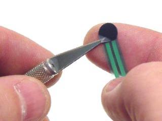 Figure 1.
Stick the adhesive side of the sensor to the inside of the gripper as shown. Make sure you position the sensor between the screw holes.
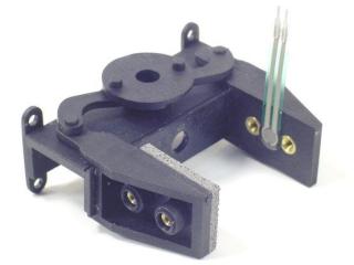 Figure 2.
Cover the sensor with electrical tape. This will help hold it down.
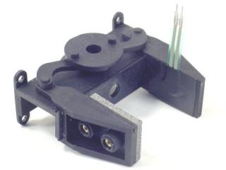 Figure 3.
Peel an adhesive-coated bumper off of the paper and stick it firmly over the sensor as shown. Centre it precisely on top of the FSR — clear rubber bumpers are used to make this easier.
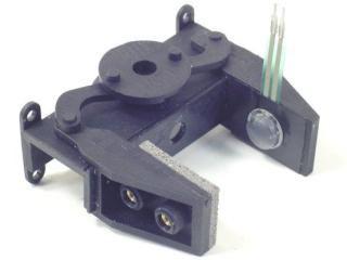 Figure 4.
There are several ways to use an FSR. Depending on the configuration, the values returned will differ. Remember to use heat shrink to avoid shorts!
- For standalone arms, use the Basic Config section of Figure 5.
- For arms on an A4WD1 rover, use the Other Config section of Figure 5.
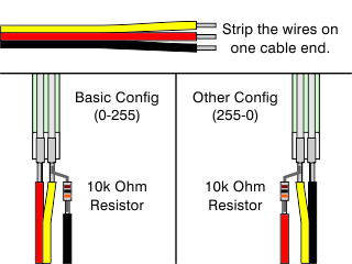 Figure 5 — Wiring diagram.
Refer to the following chart for expected pressure vs. voltage values.
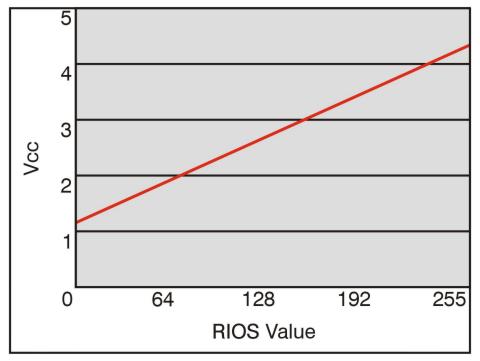 Pressure vs. voltage chart.
Attach two 3mm screws in the screw holes as shown. Don't tighten too much or the sensor will bend. Carefully bend the sensor wires to lie between the screws — do not bend the sensor tail too sharply. Secure the sensor tail and wires with a wire tie as shown.
Mount the gripper onto the arm and route the sensor wires.
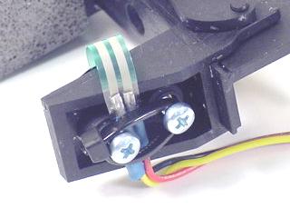 Figure 6.
For RIOS / SSC-32: Remove the yellow wire from the housing and cover it with heat shrink to prevent shorts. Plug the black wire into (−), the red wire into (+), and the white wire into input A, B, C, or D as shown in the diagram.
For Bot Board (no RIOS): No cable modification needed. Plug the cable into AX0–AX3. Ensure the yellow wire goes toward the centre of the board.
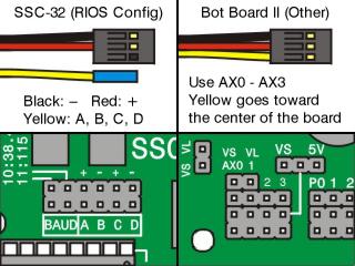 Figure 7 — Connection diagram.
Run RIOS and click the "SSC-32" button in the upper left corner. Select "A" on the sensor input corresponding to the pin you plugged the sensor into. Gently press the sensor to test connectivity — you should see a bar indicating sensor pressure. Save and exit when done.
 Figure 8.
Click "Moves". Press the black + in the projects section to create a new project. Use the gripper close button (upper right) to close the gripper completely, then press the green + in the step section to add this as a new step.
Change the "no input action" dropdown to "stop this step" and select the input corresponding to the pin your sensor is plugged into.
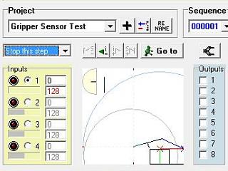 Figure 9.
Press the green + in the step section to create a new step. Enable "gripper load" — the gripper button just above the Outputs section. When enabled, the gripper picture will show a red ball being held.
While gripper load is enabled, the gripper will not open or close again until it is disabled. This allows the arm to skip gripper steps until the object is deposited.
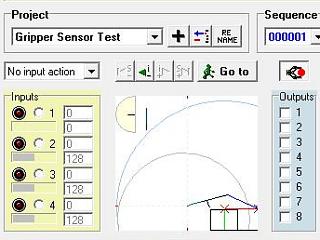 Figure 10.
Use the gripper open button (upper right) to open the gripper completely. Press the green + in the step section to add the opened gripper as a new step. Now disable gripper load — this will allow the gripper to open again. Click "Play" in the lower right corner.
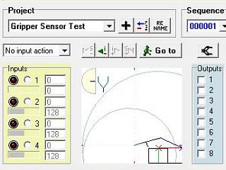 Figure 11.
Press the "Play" button (upper left) and test your project. When the gripper starts to close, place an object inside or press against the sensor. Once the threshold is reached, the gripper will stop closing and begin to open.
To adjust the threshold, click "Exit" and change the value in the Inputs section of Step 2. For a more complex example, load the project "Demo 09 Grip Close".
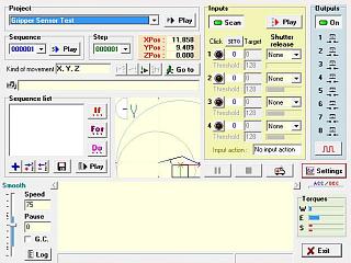 Figure 12.