
Humanoid Biped Leg Pair Assembly Guide
Humanoid Biped Leg Pair Assembly Guide
Updated August 30, 2007
Hardware: 4x Multi-Purpose Servo Bracket Two Pack (ASB-04) · 5x "C" Servo Bracket w/ Ball Bearings Two Pack (ASB-09) · 1x Alum. Robot Feet Two Pack (ARF-01) · 8x HS-5645 Digital Standard Servo (S5645MG)
Goal: Assemble a pair of humanoid biped legs using servo brackets.
Notes: This guide covers one leg for the robot's right side. Repeat all steps as a mirror image for the left leg. This is only an example — there are countless other configurations with fewer degrees of freedom, tubing, etc.
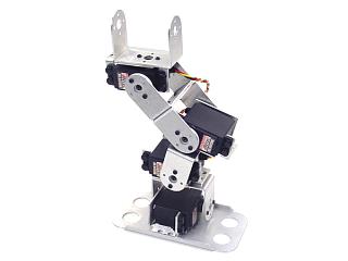
Humanoid Biped's Right Leg.
Attach a multi-purpose servo bracket to a "C" bracket as shown using two 2-56 x .250" screws and 2-56 nuts.
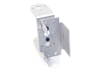 Figure 1.
Attach two "C" brackets together as shown using two 2-56 x .250" screws and 2-56 nuts.
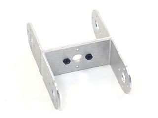 Figure 2.
Connect the "C" bracket to the multi-purpose bracket as shown. Refer to Figure 3-1 for ball bearing detail.
Figure 3-1 — Ball bearing detail.
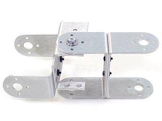 Figure 3-2.
Attach a multi-purpose servo bracket to a "C" bracket as shown using two 2-56 x .250" screws and 2-56 nuts.
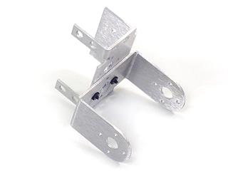 Figure 4.
Connect the "C" bracket to a multi-purpose bracket as shown. Refer to Figure 5-1 for ball bearing detail.
Figure 5-1 — Ball bearing detail.
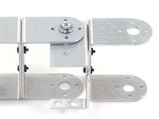 Figure 5-2.
Attach a multi-purpose servo bracket to a "C" bracket as shown using two 2-56 x .250" screws and 2-56 nuts.
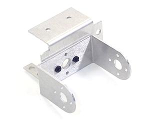 Figure 6.
Connect the "C" bracket to a multi-purpose bracket as shown. Refer to Figure 7-1 for ball bearing detail.
Figure 7-1 — Ball bearing detail.
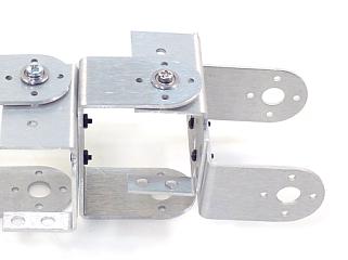 Figure 7-2.
Attach a multi-purpose servo bracket to the foot panel as shown using three 2-56 x .125" countersunk screws and 2-56 nuts.
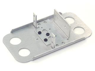 Figure 8.
Connect the "C" bracket to the multi-purpose bracket as shown. Refer to Figure 9-1 for ball bearing detail.
Figure 9-1 — Ball bearing detail.
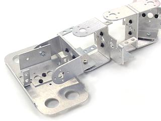 Figure 9-2.
Attach all servos as shown using the included 3mm hardware and two #2 tapping screws each. Rivet fasteners (NSRF-01, sold separately) can be used for quick prototype assembly.
 Figure 10 (completed leg).
When ready to attach the legs to your biped torso, attach the "C" brackets as shown using the ball bearing hardware and four #2 tapping screws.
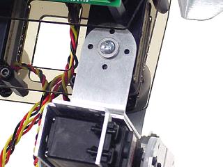 Figure 11.