SES-PRO Robotic Arm UI Guide
Quickstart Flow | |||||
| Arm model | Arm COM Port | Connect | Gripper Model | Gripper COM Port | Gripper Connect |
|
|
|
|
|
|


Before proceeding with the guide, it is important to note the following:
It's a good thing to practice with the software without an Arm connected, that way you can learn safely. | ||
| Pressing the i "Information" icon in the software will bring you to the SES-PRO Robotic Arm UI page. | |
IMPORTANT | ||
Payload Considerations | ||
| ||
Emergency | ||
| Before using the arm, it is important that a user know what to do when an issue or emergency arises where the arm must be stopped quickly. The following emergency options are available based on severity: | ||
| Halt (and hold) This will stop every joints and hold them in their last recorded angular positions. The corresponding command is #254H<cr>. | |
| Limp All joints will go limp which mean there will be nothing avoiding them to turn freely (potentially causing the arm to fall). The high gear ratio of the strain wave gearing does mean there is some (low) level of resistant to rotation, but the gears and motor are not "locked" and as such, the arm may fall. The corresponding command is #254L<cr>. | |
| Software E-Stop The E-stop button within the software sets all joints to limp, this can possibly cause the arm to fall. | |
Power Supply E-Stop A hardware E-stop (push to cut power) button is located on the power supply which will cut electricity to all actuators. Similar to a limp command, this can possibly cause the arm to fall. To reset this button, rotate the red "mushroom" in the direction indicated by the white arrows and it will spring out. | ||
Robotic Arm | ||
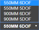
| Model The software currently supports the following Lynxmotion PRO Arms:
In practice, each 5DoF arm has joint 4 at a fixed angle, otherwise the arms are identical to the 6DoF. Users can always purchase the missing actuator to upgrade to a 6DoF. | |
| COM Port The first joint at the base (J1) must be connected via USB to a computer running the sofware. No other joints should have a USB connection. A USB 3.0 port or higher on the computer is suggested, as the lower communication speeds fo USB 2.0 or 1.0 may impede communication and cause unecessary delay or issues. | |
| Connect / Disconnect Once the COM port has been selection, the CONNECT button can be pressed, and once a servo has been found, the light next to it will go from red to green. | |
Gripper | ||
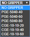
| Model The software currently supports two models of Lynxmotion PRO compatible grippers based on DH Robots' PGE-50-40 and CGE-10-10 electric grippers. The Lynxmotion kits include hardware to mount the fingers in multiple different offsets for smaller or larger objects. In the sequencer, the position of the fingers for each gripper are included in the sequencer as G. | |
|
| |
| COM Port Choose the appropriate COM port to which the gripper is connected (via its own USB cable). If you are not certain, you can check Windows -> Device Manager | |
| Baudrate The DH Robotics grippers provide the option to change the baud rate, though the default is 115200. If the gripper is configured by the user to a different baud rate, it is important to select the corresponding baud rate in the software. | |
| Connect Pressing CONNECT establishes a connection to the gripper and goes through the initilization process once, opening the gripper fully. Once connection has been established, the light next to the button will go from red to green. | |
| Initialize Initializing the gripper opens it fully. This is available should the user encounter issues with positioning and need to re-zero the fingers.
| |
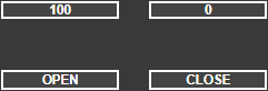
| Position Actual opening of the gripper in percent.
| |
| Speed Speed at which the gripper will travel.
| |
| Force Maximum force exerted by the gripper
| |
| Open / Close These are shortcut buttons to either open or close the gripper. The fields can be set to the desired position for either Open or Close. | |
Sequencer The sequencer displays the gripper position as joint G. Ex: #GP1000 HINT: If you want the gripper to open or close on an object only at the end of a motion, create a separate frame where only G moves. | ||
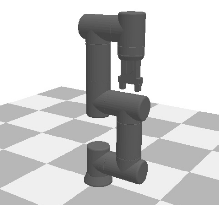
3D Model | ||
The 3D model of the arm is shown as reference at all times. The display also includes a virtual plane to denote the X-Y plane. The model updates based on the selection of the arm, gripper and finger configuration. | ||
| View Controls Zoom: Shift + Middle Scroll Rotate: Shift + Middle Mouse and mouse movements Pan: None | |
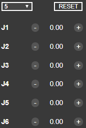
Manual Move | ||
| Joints Control (angular) In Joints mode, the user can control the angle of each joint.
| |
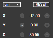
| Coordinates Control In coordinate control the user can control the cartesian position of the end effector | |
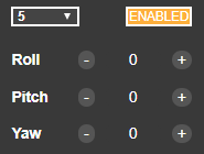
| End Effector Lock The orientation of the end effector can be locked with the "ENABLED" button. | |
Direct Command | ||
This section allow the user to send commands using the LSS-PRO Communication Protocol directly if required. A few things to keep in mind when using this:
| ||
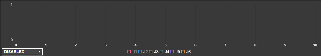
Telemetry | ||
| ||
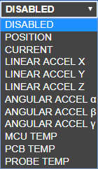
| Data to Display Various telemetry data can be retrieved from each actuators / joints, here is what the software support:
| |
| Display / Hide At the bottom of the graphics you will find squares to activate / deactivate the desired actuator / joint to be displayed in the graph. | |
Sequencer | ||
Sequence That's where you can create and edit the sequence you need to play in your particular project. | ||
| Sequence Selector Multiple sequences can be open at once and this is where you will be selecting which one will be displayed and/or played. | |
| Add Create a new Sequence that will be automatically selected. | |
| Subtract Remove / Delete the currently selected Sequence. | |
| Copy Create a copy of the currently selected Sequence and add a "- copy" to it's name. | |
| Save Saving the currently selected sequence for future use. | |
| Open Opening a previously saved sequence. | |
| Delete Deleting the ALL sequence leaving an empty "Sequence 1" | |
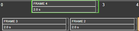
Frames Those are frames or cards that will allow to move to specific positions. The user can either modify them by clicking on the Record button or manually edit them. | ||
| Add Create a new frame / card in the selected sequence. | |
| Add frames from Sequence Will add the frame present in another sequence to the currently selected one. This is useful if you want to isolate some sequences and test them out alone than combine them in a master Sequence. | |
| Record Store the current positions of each joints including the gripper in the selected frame / card. | |
| Remove Delete the currently selected frame / card. | |
| Copy Copy all the positions from the selected frame / card. | |
| Paste Paste all the position from the previously copied frame / card to the selected one. | |
| Invert Invert the frame / card so the First one become the Last and everything in between too. | |
| Frame
| |
| Frame Position Moving your cursor to the upper part of the frame will display a "hand" and then you can drag & drop the frame into a new position to re-order them. | |
| Starting Frame A start frame is required to calculate the speed for the first frame / card. This is usually the Zero point with all actuators being a 0deg but it's possible to make it yours by changing it manually or with the record button. Note: This frame will always be played at a fixed speed for all actuator which means they will not Stop at the same time. | |
| Loop The amount of time you want the particular sequence to play. If you click on the "Loop" test it will become Infinite. | |
| Manual Edit Manually create or edit an already made frame / card in this window. Each joints and gripper can be modified that way. | |
| Zoom Allow you to zoom In or Out making the time resolution change. Something nice when dealing with long sequences. | |
| Play from Start Start the sequence selected at the beginning. | |
| Play Start the sequence selected at the beginning OR where it was when Pause was pressed. | |
| Pause Only displayed once the sequence is started (play) and allows the user to pause the sequence anywhere.
| |
| Stop Stop the sequence & hold position. | |