Modifying a Project from the App Store
| Modifying a Phidgets App | |
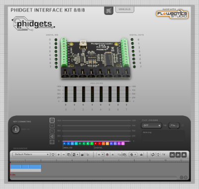
If you want to learn FlowBotics Studio by modifying an existing app, the Phidgets series of Apps were designed to be make this very easy. When you open the project in the FlowBotics Studio schema editor, you will see its front panel: | |
| |
| If you double-click its border to open its schematic, you will see the following: | |
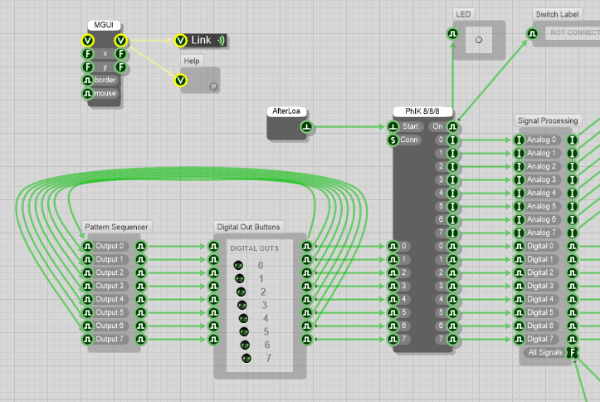 | |
| There may seem to be a lot of things going on, but after a minute examining it, you will understand how it works. | |
| Layout | |
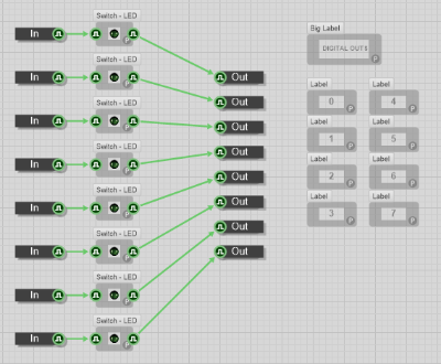
The most important part is the "PhIK 8/8/8" component in the middle-right of the image. It is dark gray because it's a Primitive, a type of component which cannot be modified. On its left side is the digital output signals. The green links provide signals into the component, which are then output from the board. The inverse is true about the right side: signals input into the board are output by the component. The two components in the bottom-left of the image are light gray because they're Modules, a component that has its own schematic that can be edited. In this case, the "Digital Out Buttons" provides a simple user interface for turning On and Off each of the digital outputs. | |
 | |
The "Pattern Sequencer" module does a lot more heavy-lifting: it's the one that provides the functionality for creating output sequences and playing them. When it is playing a sequence, it uses its outputs to send signals to update the buttons, which in turn send signals to update the board. Since it needs to know state of the digital outs to record them, the module also receives the button signals to its inputs, which explains the loops. On the right side of the schematic, there's more modules for the inputs of the board. The "Signal Processing" module is a place to do things such as adding debounce code or adding a moving average function. The "Analog Input Displays", "Digital Input LEDs", "History", and "Data Logger" modules (offscreen) provide user interfaces for the signals and functionality for logging to a file. | |
Making a First Change | |
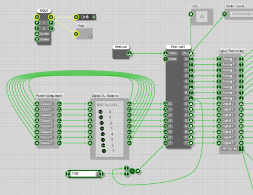
Imagine you have a temperature sensor connected to one of the analog inputs, and you would like to turn on one of the digital outputs to sound a buzzer when the temperature is too high. Based the datasheet of the sensor, you determine that the sensor will output 3.5 volts when at that temperature, which is a value of 700 on the 1000 point scale of the Phidget board. Changing the schematic to do this is very easy.
| |
 | |
More Changes | |
You now know the basics and can make more changes to the project to make the Phidget 8/8/8 board do exactly what you want. If you have any questions, or would like to share your ideas, we encourage you to do so in our forum and we'll get back to you very quickly! | |
| << Back to Developer Zone |