A-Pod 3DoF Bot Board II / BASIC Atom Pro Tutorial
| A-Pod Bot Board II / BASIC Atom Pro Tutorial.
Updated 08/10/2010. Phoenix code v2.0. Safety first! Wear eye protection and never touch a powered robot! Software: |
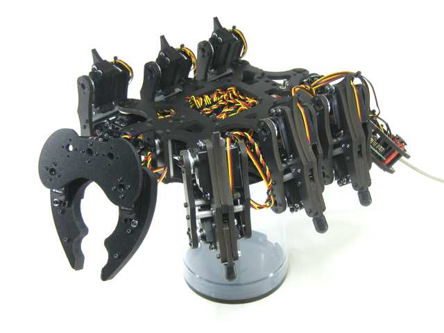
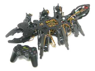 Image of A-Pod. |
||||||||||||||||||||||||||||||||||||||||||||||||||||||||||||||||||||||||||||||||||||||||||||||||||||||
|
I. SSC-32 Configuration: Registers |
|||||||||||||||||||||||||||||||||||||||||||||||||||||||||||||||||||||||||||||||||||||||||||||||||||||||
|
Step 1. Download and install the latest version of LynxTerm. |
|
||||||||||||||||||||||||||||||||||||||||||||||||||||||||||||||||||||||||||||||||||||||||||||||||||||||
Step 2. To test basic communications, do a "ver" test: type "ver" into the terminal then press "Enter". You should see the proper firmware version returned. Please consult the serial troubleshooting guide if you have difficulties with this. |
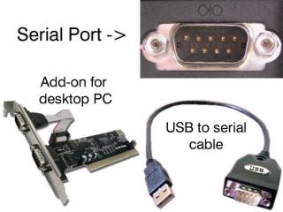 Figure 2. |
||||||||||||||||||||||||||||||||||||||||||||||||||||||||||||||||||||||||||||||||||||||||||||||||||||||
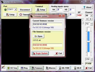
| Step 3. Download the 2-07EGP_A1A.abl firmware or higher. Make sure the baud rate is set to 115.2k before attempting to update. Refer to the manual if you need more information regarding baud rate. Click on "Firmware" along the bottom of the LynxTerm screen. Click on "Open" and browse to the firmware file you just downloaded. Make sure the SSC-32 is powered, and click on "Begin Update". |
|
||||||||||||||||||||||||||||||||||||||||||||||||||||||||||||||||||||||||||||||||||||||||||||||||||||||
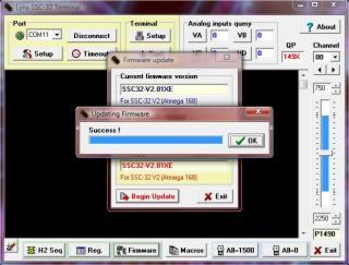
| Step 4. When the firmware has been successfully updated, click "Ok" then "Exit". Now do another "ver" test: type "ver" into the terminal then press "Enter". You should see a new firmware version returned. |
|
||||||||||||||||||||||||||||||||||||||||||||||||||||||||||||||||||||||||||||||||||||||||||||||||||||||
Step 5. Caution! You are about to power up the servos. When this is done immediately make sure all of the moving parts are not tangled or hung up and no joints are positioned beyond their range of motion. If anything looks wrong, power down and look for mechanical problems with the build. This is bot has long, apendeges. You must periodically allow the servos to cool down if left on for more then 5 minutes at a time. Take care with the vertical servos, especially the head and tail. They should be monitored to prevent overheating during the calibration. |
|
||||||||||||||||||||||||||||||||||||||||||||||||||||||||||||||||||||||||||||||||||||||||||||||||||||||
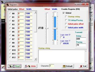
| Step 6. From the main screen, click on "Reg" to open the Registers page. Click on "Default" to initialize default values. |
|
||||||||||||||||||||||||||||||||||||||||||||||||||||||||||||||||||||||||||||||||||||||||||||||||||||||
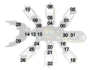
| Refer to this servo channel number guide for the following configuration steps.
Do the most accurate alignment as possible! The robot can only operate as well as as it is aligned. In other words, a poorly aligned robot will walk poorly! |
|
||||||||||||||||||||||||||||||||||||||||||||||||||||||||||||||||||||||||||||||||||||||||||||||||||||||
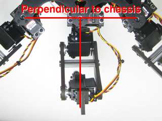
| Step 7. You need to adjust the robot's horizontal hip servos. Select servo #04, then adjust the "Offset" slider until the leg is perpendicular to the robot's chassis as shown. Do this for servos #04 and 20. Note, the mouse's scrollwheel or keyboard's arrow keys can be used to make fine adjustments. |
|
||||||||||||||||||||||||||||||||||||||||||||||||||||||||||||||||||||||||||||||||||||||||||||||||||||||
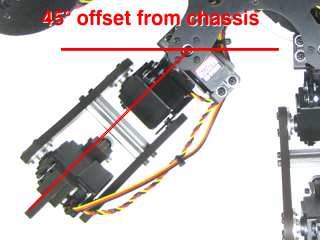
| Step 8. You need to adjust the robot's remaining horizontal hip servos. Select servo #00, then adjust the "Offset" slider until the tibia is at a 45° angle from the robot's chassis as shown. Do this for servos #00, 08, 16, 24. Note, the mouse's scrollwheel or keyboard's arrow keys can be used to make fine adjustments. |
|
||||||||||||||||||||||||||||||||||||||||||||||||||||||||||||||||||||||||||||||||||||||||||||||||||||||
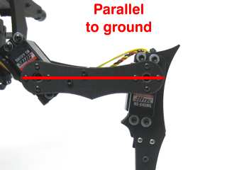
| Step 9. Now adjust the robot's vertical hip servos. Select servo #1, then adjust the "Offset" slider until the robot's femur is parallel to the ground as shown. Do this for servos #01, 05, 09, 17, 21, 25. |
|
||||||||||||||||||||||||||||||||||||||||||||||||||||||||||||||||||||||||||||||||||||||||||||||||||||||
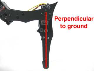
| Step 10. Now adjust the robot's knee servos. Select servo #2, then adjust the "Offset" slider until the tip of the robot's foot is directly underneath the knee servo pivot point. From the servo's pivot point to the tip of the foot should be perpendicular to the ground as shown. Do this for servos #02, 06, 10, 18, 22, 26. |
|
||||||||||||||||||||||||||||||||||||||||||||||||||||||||||||||||||||||||||||||||||||||||||||||||||||||
Step 11. |
|
||||||||||||||||||||||||||||||||||||||||||||||||||||||||||||||||||||||||||||||||||||||||||||||||||||||
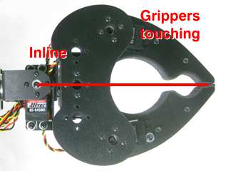
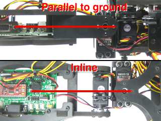
| Step 12. Now adjust the remaining mandible servos. Adjust servo #12 until the mandibles are inline with the chassis. Adjust the two gripper servos (#28 and #29) so that they just barely touch each other, as shown. It is important for the gripper servos to not be straining against each other. |
|
||||||||||||||||||||||||||||||||||||||||||||||||||||||||||||||||||||||||||||||||||||||||||||||||||||||
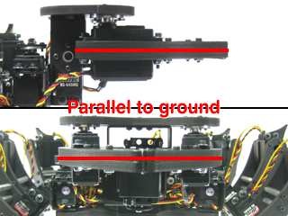
| Step 13. Now for the robot's abdomen servos. Adjust #30 until the abdomen is inline with the chassis. Adjust #31 until the abdomen is parallel to the ground. |
|
||||||||||||||||||||||||||||||||||||||||||||||||||||||||||||||||||||||||||||||||||||||||||||||||||||||
|
II. Bot Board II Configuration |
|||||||||||||||||||||||||||||||||||||||||||||||||||||||||||||||||||||||||||||||||||||||||||||||||||||||
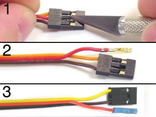
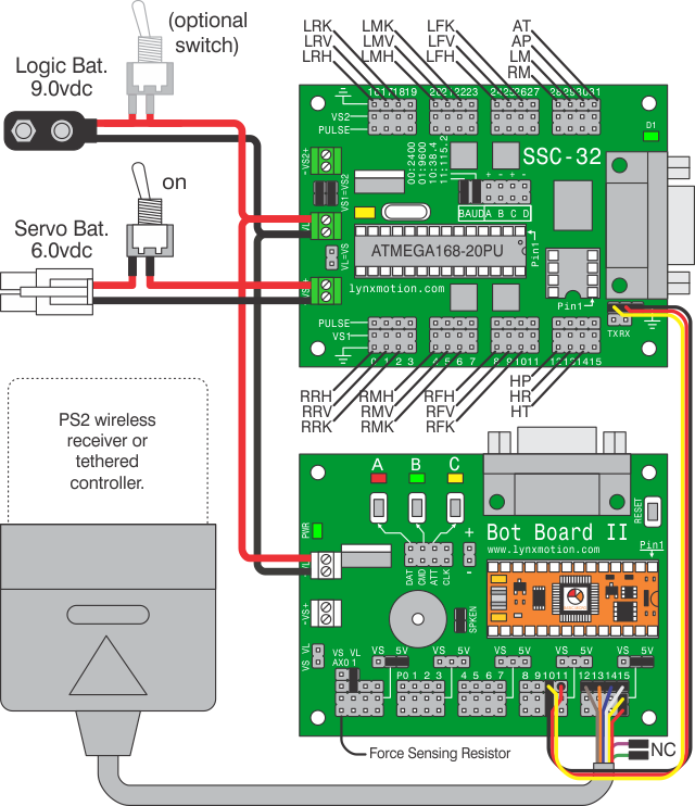
Step 14. Remove the TX and RX jumpers from the lower-right corner of the SSC-32, and plug the unmodified end of the cable in. Yellow on TX, red on RX, and black on ground. Plug in some extra lengths of 18-24awg wires to VL on the SSC-32, with the 9vdc battery clip. These will be used to run power to the Bot Board II. See Tables 15-2 through 15-4, and the schematic below for connection information. |
|||||||||||||||||||||||||||||||||||||||||||||||||||||||||||||||||||||||||||||||||||||||||||||||||||||||
|
|
|||||||||||||||||||||||||||||||||||||||||||||||||||||||||||||||||||||||||||||||||||||||||||||||||||||||
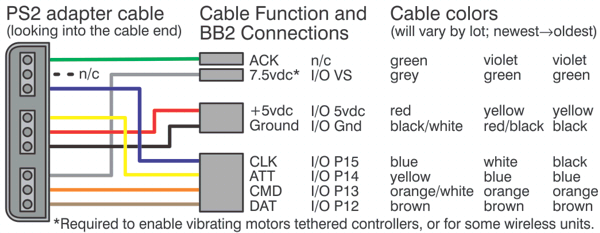
| Step 15. Plug the modified end of the servo to the Bot Board II. The yellow and black part goes on pin 10 with the black wire toward the outside of the Bot Board II. Plug the red wire in on Pin 11, on the header pin nearest the center of the Bot Board II. Plug in the PS2 cable as shown in Figure 15-1. Plug in the power wires from the SSC-32 to VL. Note: Refer only to Figure 15-1 for connection information. The cable colors in the picture may be outdated. If your cable's colors do not match the diagram, you can find a complete listing of possible colors here. See Tables 15-2 through 15-4, and the schematic below for connection information. Install the BASIC Atom Pro as shown.
|
|||||||||||||||||||||||||||||||||||||||||||||||||||||||||||||||||||||||||||||||||||||||||||||||||||||||
|
Connection Information Tables.
|
|||||||||||||||||||||||||||||||||||||||||||||||||||||||||||||||||||||||||||||||||||||||||||||||||||||||
|
Schematic. Schematic. |
|||||||||||||||||||||||||||||||||||||||||||||||||||||||||||||||||||||||||||||||||||||||||||||||||||||||
Step 16. Download the Program Download the .zip file, and unzip it. Open the .prj file in Studio (File->Open->*.prj), and verify that the files listed in the Workspace are in the order shown in Table 16. Install the PS2 controller receiver into the PS2 cable on the robot, make sure your PS2 controller is turned on, and then apply power to the robot. Program the Atom Pro. If all is well, you will hear a beep after power up. Press Start and the legs should snap to position. At this point, if you properly calibrated the servo offsets, the legs should be perfectly aligned. Note: The software switches the controller to analog mode. However, some controllers may need to be put into analog mode manually. If you hear a continuous beeping, the PS2 controller is not connected to the Atom properly or is not functioning. If you hear beeping, you can try pressing Reset on the Bot Board II. You can also test the controller with a Playstation 2 to verify that it is working. |
|
||||||||||||||||||||||||||||||||||||||||||||||||||||||||||||||||||||||||||||||||||||||||||||||||||||||
| Step 17. Controlling the
Robot with PS2 Controller The default is Walking mode 1. Use the Left joystick to move the robot around without turning (this is called "translation"), and the Right joystick rotates the robot as it moves. Up and Down on the D-Pad increases or decreases the height of the body. The Triangle button puts the body at 35mm from the ground. The Triangle swaps between a walking stance and a 'resting' position. There are two special "body moves" functions that are triggered by pressing Circle, or X. While in one of these modes, the hexapod does not walk. The joysticks and some buttons change function depending on which mode is toggled on; see Table 17 for details. |
|||||||||||||||||||||||||||||||||||||||||||||||||||||||||||||||||||||||||||||||||||||||||||||||||||||||
|
PS2 Controls
Table 17. |
|||||||||||||||||||||||||||||||||||||||||||||||||||||||||||||||||||||||||||||||||||||||||||||||||||||||


