
A-Pod 3DoF Mandibles Assembly Instructions
The A-POD Gripper Assembly Guide
Updated November 17, 2011
Removing the Parts from the Panel
The PVC parts need to be carefully cut out of the panel. A thin, flat blade exacto knife will be very helpful. Simply cut through the tabs to remove the parts.
Important!
DO NOT overtighten screws on the PVC parts! The PVC will compress and will become weaker as a result.
Preparation
Remove the nylon servo horn from each servo and replace with a metal servo horn. Be sure to keep it in the same orientation.
Attach a ball bearing to two Multi-purpose brackets as shown. See the diagram below for detailed information. Make one of each.
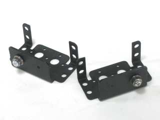 Figure 1-2.
Attach the two brackets together as shown using two 2-56 x .25" screws and two 2-56 nuts.
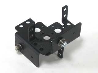 Figure 2.
Attach a "C" bracket to the top panel with four 2-56 x .375" screws and 2-56 nuts.
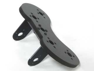 Figure 3.
Slide the "C" bracket over the ball bearing.
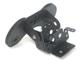 Figure 4.
Slide a HS-645 servo into the bracket and secure it using 3mm hardware as shown. Attach it to the "C" bracket with four 2-56 x .25" screws.
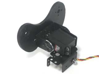 Figure 5.
Attach two pincer panels to a servo as shown. Set this aside for now.
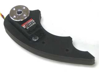 Figure 6-2.
Slide the plastic spacer into place as shown. Tighten it down between a washer and nut if you have trouble simply pushing it in. Remove the screw when the insert has been installed. You will be adding the force sensing resistor to this servo.
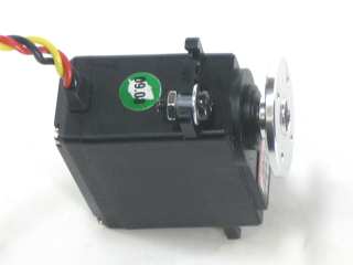 Figure 7.
Strip off one end of the 24" servo extender cable and solder as shown. Use heatshrink to cover the bare wire.
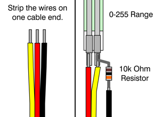 Figure 8.
The sensor leads can be fragile when bent often or excessively. Use the included piece of heatshrink to help protect the lower portion of the sensor.
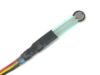 Figure 9.
Use an exacto knife to carefully peel away the clear plastic piece covering the black adhesive. Be very careful — if not done carefully the sensor can be damaged!
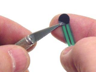 Figure 10.
Attach the sensor to the servo as shown.
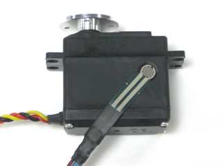 Figure 11.
Apply a layer of electrical tape over the sensor to help hold it down.
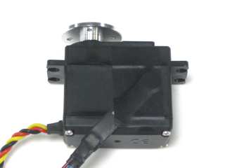 Figure 12.
Place four more thin strips of electrical tape onto the sensor. This will fill the gap between the sensor and the inside of the servo slot and make the sensor trigger more reliably.
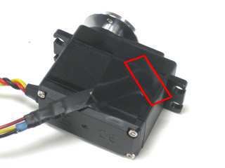 Figure 13.
Attach two pincer panels to the servo with the sensor as shown. Do not tighten these down fully. In order for the pressure sensor to function properly, the servo needs to be loose enough to shift slightly.
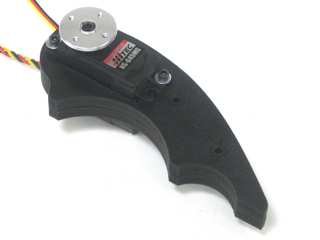 Figure 14-2.
Make sure the pincer panels are aligned, then reinforce them using two 4-40 x .625" hex screws and nuts each.
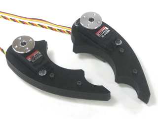 Figure 15.
Attach the pincers to the top panel with four 2-56 x .375" screws each.
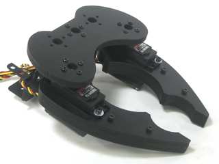 Figure 16.
Attach a HS-645MG to the robot using 3mm screws, washers and nuts.
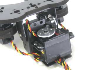 Figure 17.
Attach a "C" bracket to the 1" spacer in the front of the chassis using four 2-56 x .250" screws.
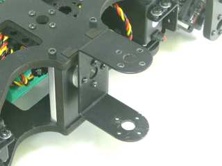 Figure 18.
Slide the gripper assembly into place in the "C" bracket on the front of the chassis. Connect the servo horn to the "C" bracket using four 2-56 x .250" screws.
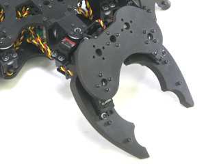 Figure 19.
Clean the pincers using a cloth with isopropyl alcohol. Attach two pieces of weather stripping to the insides of the mandibles as shown. If the surface has not been cleaned, the strips will not stick to the material.
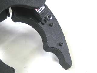 Figure 20.