
CH3-R "The Wicked One" Mod
"The Wicked One" CH3-R Mod
Updated November 8, 2006
This is the first tutorial of a series planned for this robot. This tutorial illustrates how to hack the Playstation receiver to take up less space, with the added benefit of adding two red LED "eyes" to the bot.
First disassemble the robot by removing the top panel and moving the Bot Board off to the side, out of the way. Install some 1" standoffs (cut down to 7/8") onto the SSC-32.
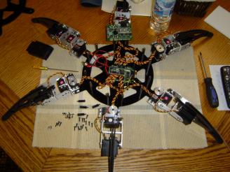 Figure 1.
Mount the Bot Board onto the SSC-32 using MF 3/4" standoffs. This allows all of the electronics to be installed inside the robot's chassis.
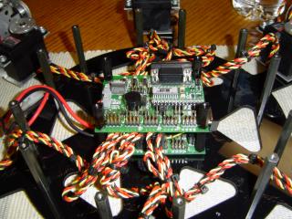 Figure 2.
Disassemble the PS2 receiver and remove the large connector on the left of the board.
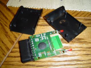 Figure 3.
Cut the plug off of the PS2C-01 cable, strip the wires, and solder them onto the receiver module.
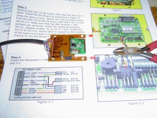 Figure 4.
Reassemble the receiver. The image shows the completed modified receiver.
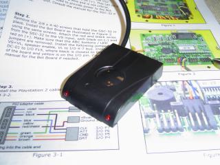 Figure 5.
Reattach the top panel and connect the Bot Board and SSC-32 to it.
 Figure 6.
Use a little double-sided tape to hold the receiver onto the top panel.
 Figure 7.
Install the power switch and put in a battery.
 Figure 8.
The completed "Wicked One" robot.
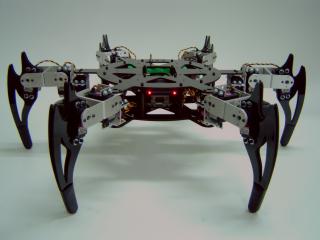 Figure 9.