
MHBKR Body Assembly Instructions v1.0
MHBKR Body Assembly Instructions Rev. 1
Updated November 6, 2012
Safety first! Wear eye protection and never touch a powered robot!
The purpose of this guide is to construct the chassis, attach the legs, and install the electronics. Images show the MAH3-R (Mega AH3-R Hexapod); the procedure is the same for all kits using this body.
Note: the MHBKR is a larger version of the HBKR and is part of the H3 series. All electrical and programming tutorials for the H3-R series can be used.
Use the 4-40 x 1/4" hex socket screws to attach the 12 aluminum hex spacers to the bottom panel.
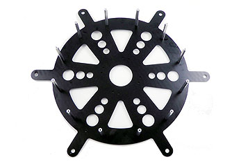 Figure 1.
Use four 4-40 x 1/4" hex socket screws to attach four 4-40 x 3/8" M/F plastic hex spacers to the bottom panel as shown. Note: the bottom panel is symmetrical — there is no front or back.
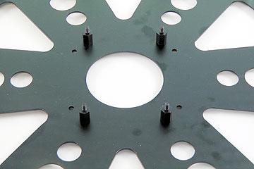 Figure 2.
Configure the SSC-32 for 115.2 kbaud and DB9 communication. Remove the VL=VS jumper and both VS2=VS1 jumpers. Consult the SSC-32 manual if needed.
Attach the 9V battery wiring harness to VL to power the electronics. Depending on your kit, you may also need to connect the ~8" twisted wire to VL. Make sure red wires go to (+) and black wires go to (−). Put electrical tape on the free wire end for now. Attach a battery connector to VS1 and a second battery wiring harness to VS2.
Note: two main battery connectors are used since the 755 servos consume a lot of current.
Schematic. Double check your connections against the schematic below.
| Servo Letter Definitions | ||
|---|---|---|
| Left Right |
Rear Middle Front |
Knee Vertical Horizontal |
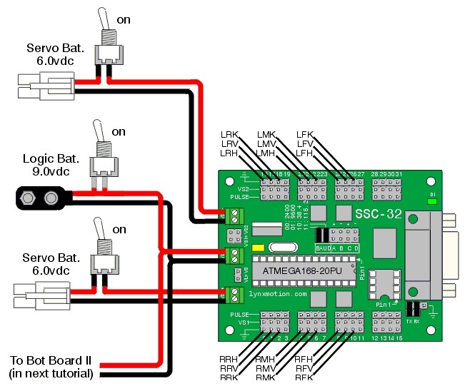
Schematic 3-1.
Slip the SSC-32 onto the 4-40 x 3/8" hex spacers as shown.
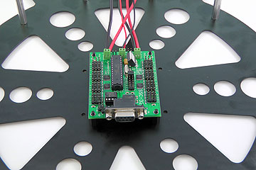 Figure 4.
Plug the servos into the SSC-32 as illustrated in Figure 5. Simply plug in the servo associated with the function to the corresponding pin. If oriented correctly, the I/O port (group of four pins) will be closest to its corresponding leg.
The orientation of the three-wire connector is important: yellow wire to signal, red wire to V, black wire to GND.
Follow steps 2–4 from the H3 BotBoarduino Guide to connect the BotBoarduino to the SSC-32. If you did not purchase the PS2 option, skip the relevant schematic.
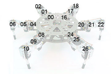 Figure 5.
Attach the 1" x 4-40 hex spacers to the 3/8" hex spacers. Connect the second board (Bot Board or BotBoarduino) to the 1" spacers using four 4-40 x 0.250" screws. Power and signal connections are not shown in Figure 6 for clarity, but yours should be connected.
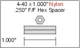
 Figure 6.
Install the top plate, ensuring the rectangular opening lines up with the board. The three small holes should be on the side with all the wires. Leave the screws a little loose for now.
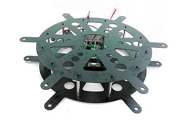 Figure 7.
Install the three power switches to the top plate. The switches come with all the hardware needed. Be sure to mount them all in the same orientation (one side for ON, the other for OFF).
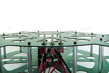 Figure 8.
Install all the legs. You will need to: (a) loosen the screws, (b) insert the bearing into the hole, (c) insert the servo between the top and bottom plate, and (d) connect the servo horn at 0° to the top plate (perpendicular). Refer to Figure 9 for clarification. The bearings and associated hardware should be used with the leg assembly guide.
This completes the mechanical assembly. You can now move on to the Complete H3/H3-R Tutorial.
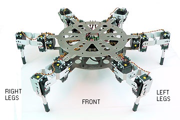 Figure 9.