
T-Hex 3-4DoF Body Assembly Instructions
The T-HEX Body Assembly Guide
Updated August 17, 2011
Important: This assembly guide applies to BOTH the 3DOF and the 4DOF T-HEX models, even though the pictures use 3DOF legs.
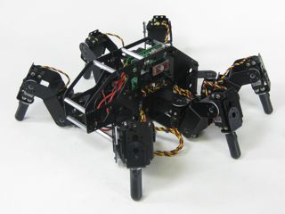
Image of 3DOF T-HEX.
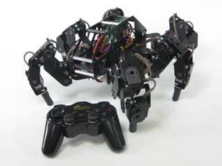
Image of 4DOF T-HEX.
Attach two 1/4" standoffs to the base panels as shown using two 2-56 x .250 screws each.
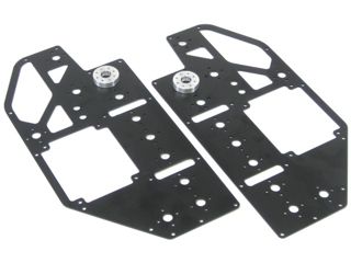 Figure 1.
Connect twelve 1.875" hex spacers to the right chassis panel as shown using 4-40 x 1/4" hex socket screws.
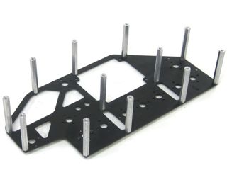 Figure 2.
Attach two "C" brackets and four Offset "C" brackets to the chassis as shown. Use two 2-56 x .250" screws and 2-56 nuts for each bracket. Note: to prevent damage to your battery, make sure the screws are facing the inside of the "C" brackets.
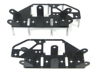 Figure 3.
Connect the two halves of the chassis together using twelve 2-56 x .250 screws.
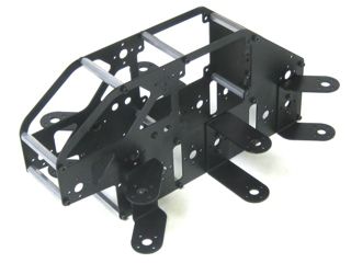 Figure 4.
Using four 4-40 x 3/8" hex socket head screws, attach the 0.75" hex spacers to the board as shown.
Configure the SSC-32 for 115.2 kbaud and DB9 communication, with the VS2=VS1 jumper installed. Remove the VL=VS jumper. Consult the SSC-32 manual if needed. Attach the wiring harness to VS1. Connect 8" of 24AWG wire (not included) AND the 9V battery clip to VL to power the electronics. Make sure red wires go to (+) and black wires go to (−).
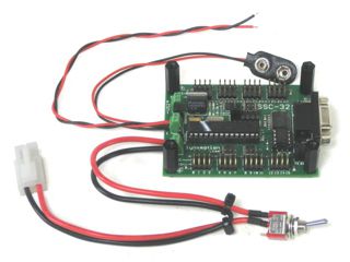 Figure 5.
Slip the SSC-32 in through the hole in the side of the robot and use four 4-40 x 3/8" hex socket screws to secure the board as shown. Make sure the DB9 port is at the back of the robot, away from the power switch hole! This ensures you can easily plug in a DB9 cable. Install the power switch in the power switch hole as shown.
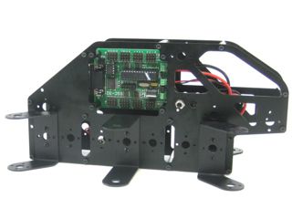 Figure 6.
Using four 4-40 x 3/8" hex socket head screws, attach four 0.75" hex spacers to the board as shown.
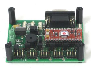 Figure 7.
Slip the Bot Board in through the hole in the side of the robot and use four 4-40 x 3/8" hex socket screws to attach it as shown. Make sure the DB9 port on the board is near the top of the robot! This ensures you can easily plug in the DB9 cable.
Attach the red and black wires from the SSC-32's VL to the Bot Board II's VL. Be sure that red goes to (+) and black goes to (−).
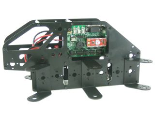 Figure 8.
Attach all legs to the chassis using two #2 x 1/4" tapping screws each.
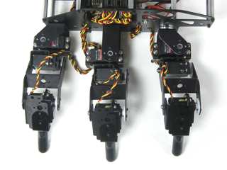 Figure 9.
Plug the servos into the SSC-32 as illustrated in Figure 10. Simply plug in the servo associated with the function to the corresponding pin. If oriented correctly, the I/O port (group of four pins) will be closest to its corresponding leg.
| Servo Letter Definitions | ||
|---|---|---|
| Left Right |
Rear Middle Front |
Horizontal Vertical Knee Ankle |
Figure 10.