
The Complete H3/H3-R Tutorial (Bot Board II) v1.0
The Complete H3/H3-R Tutorial v2.0
Updated December 20, 2011
This guide applies to the Bot Board II. The purpose of this guide is to use the PowerPod program to calibrate the servos and create a custom Basic Atom 28 or Basic Atom Pro 28 program for PS2 remote control, autonomous, or serial control.
Note: PS2 control programs have been verified to work with Madcatz, Pelican, Hiteck and Lynxmotion wireless controllers.
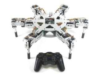
AH3-R
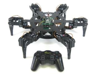
BH3-R
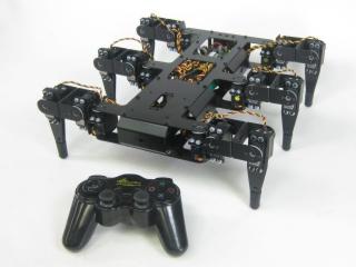
BH3
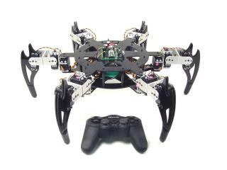
CH3-R
Hardware & Software
Hardware: SSC-32 / Bot Board II | BASIC Atom 28 or BASIC Atom Pro 28 | PS2 Cable / PS2 Wireless Controller or RC-Style Stick Radio | Hexapod 3 / 3-R
Software: PowerPod | Basic Micro Studio
Resources: Close-up of SSC-32 | Close-up of Bot Board
Download PowerPod. Unzip the file and run setup.exe — this will create a desktop icon. When the program opens, click "Help" and review the manual before proceeding.
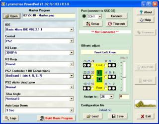 Figure 1.
Connect the serial data cable to the PC's serial port (9 pins that stick out). A BAFO BF-810 or IOGear USB-to-Serial adapter can also be used.
Please consult the serial troubleshooting guide if you have difficulties.
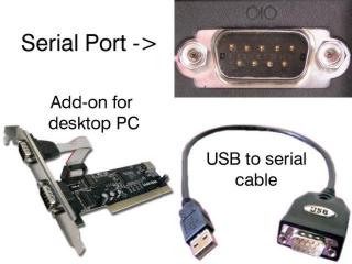 Figure 2.
Set the robot up on a stand such as a CD spindle. Connect the DB9 or USB-to-serial cable to your PC and to the SSC-32. Power up the robot. Verify that the green LED on the SSC-32 lights up — this indicates the SSC-32 is functioning properly. It remains lit until it receives serial data, then blinks when receiving data. The servos may jump but will not hold position yet. Consult the PowerPod manual if you have trouble connecting.
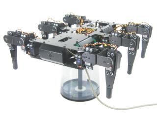 Figure 3-1.
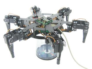 Figure 3-2.
Click "All=1500" to enable the servos. The robot's legs should move quickly into position and hold. If they go limp after moving, this indicates a low battery — the SSC-32's green LED will be steady as a clue. If the legs look radically different, remove the center servo horn screw, pull the servo horn off, reposition it, and replace the screw. Don't worry if the legs are off by less than 15° — this will be corrected in the servo offset procedure.
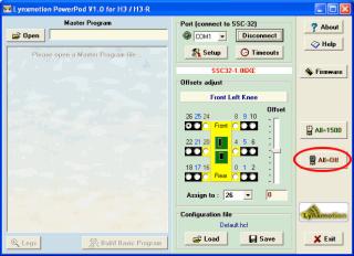 Figure 4.
Use the servo offset adjustment to fine-tune leg alignment. The goal is to align each leg perpendicular to the chassis with the knee forming a perfect right angle (see Figures 5-1 and 5-2).
Select servo channel 0 by clicking its radio button. Click once on the Offset slider to select it, then use your keyboard arrow keys for precise adjustment. Tap slowly until you see the joint move. After all joints are adjusted, save the .hcf file.
Note: the image in PowerPod represents the inline version, but servo channels are the same for the round version.
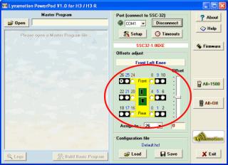 Figure 5.
 Figure 5-1.
 Figure 5-2.
Open the master .pmp program ("H3 VX.41 - Master.pmp" or newer). Check here for the most current version. Configure the following options:
IDE: Choose the appropriate version.
Control: PS2, Autonomous, or Serial.
H3 Legs: 3DOF-A, 3DOF-B, 3DOF-C, or 3DOF (Old).
H3 Body: Round or inline.
PS2 Controller / BB Connections: Bot Board I or Bot Board II.
PS2 sticks dead zone: Small, Normal, or Large.
Tibia Angle: + values set foot tip away from knee (+20 recommended for 3DOF-C leg).
Auto Legs Down: If enabled, lowers lifted tripod after inactivity.
Click Save to update your config file, then click "Build Basic Program" to create your custom program.
Figure 6.
Change the baud rate jumpers on the SSC-32 to 38.4 kbaud. Remove the DB9-enable jumpers and install the DC-01 with the narrow (0.1") spaced connector on the TTL serial communication posts. The black wire is closest to the edge of the board, and the yellow wire is on RX.
See the schematic below for detailed information.
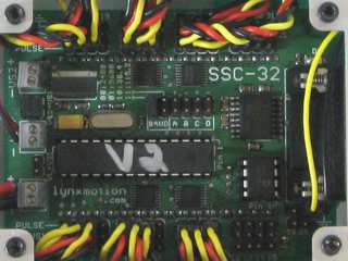 Figure 7. (click to enlarge)
For the round chassis, remove the 3/8 x 4-40 screws holding the SSC-32 and install the Bot Board using the same screws as illustrated. Attach the red and black wires from the SSC-32 to the VL input, with black on (−) and red on (+).
For both chassis styles: remove the ABC buttons / LED jumpers. Install the speaker enable jumper. Install the DC-01 to I/O P8 with black toward the outside and yellow on the I/O pin. Consult the Bot Board II manual if needed.
See the schematic below for detailed information.
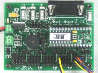 Figure 8. (click to enlarge)
Install the Playstation 2 cable as illustrated in Figure 9-1. Refer only to Figure 9-1 for connection information — cable colors in the picture may be outdated. If your cable's colors don't match the diagram, find a complete listing of possible colors here.
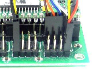 Figure 9-2.
Figure 9-1.
Schematic. Double check your connections against the schematic below.
| Servo Letter Definitions | ||
|---|---|---|
| Left Right |
Rear Middle Front |
Knee Vertical Horizontal |
Schematic.
Use some double-sided foam tape to stick the PS2 cable on the bottom of the robot as shown. This makes it easier to swap controllers if needed.
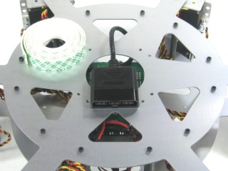 Figure 10.
Download BASIC Micro Studio. Install and run the program to allow programming the chip. Consult the serial troubleshooting guide if you have difficulties.
Open the .zip file generated from PowerPod in BASIC Micro Studio and program the Atom. Install the PS2 controller receiver into the PS2 cable, apply power. If all is well, you should hear a few short beeps, the legs should snap to position and slowly lift the body up. Then the two tripods will lift and lower once. If you properly calibrated the servo offsets, the legs should be perfectly aligned. Remove power to the robot.
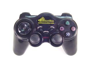 Figure 11.
Make sure your PS2 controller is on. The software switches the controller to analog mode automatically, but some controllers may need this done manually. Continuous beeping means the PS2 controller is not connected — test the controller with a PlayStation 2 to verify it works.
The shoulder buttons (L1, L2, R1, R2) adjust height, leg lift, and speed. The default is Walking mode. Use the Right joystick for translation and the Left joystick X-axis to rotate. Left joystick Y-axis changes ride height. Press Select to switch between Walking and Body Move mode.
By attaching a servo to Pin 31, it auto-pans in the walking direction. Servos on Pins 29 and 30 add pan/tilt or gripper control in Body Move mode.
| Button | Walking Mode (default) |
|---|---|
| Select | Switch modes |
| Right Joystick | Speed and direction for translation |
| Left Joystick | X-Axis: Rotational movement | Y-Axis: Ride height |
| L1 | Preset: Tile Floor |
| L2 | Preset: Default |
| L3 | Locks ride height |
| R1 | Preset: Tall Grass |
| R2 | Preset: Body Low |
| R3 | Horn |
| Start | Knee angle shift (max ground clearance) |
| D-Pad L/R | Left: Speed increase | Right: Speed decrease |
| D-Pad U/D | Up: Leg lift increase | Down: Leg lift decrease |
| △ Triangle | Lowers body then removes servo pulses. Press again to return (cold start). |
| O Circle | All servos = 1500mS |
| X | "Attack Mode" |
| □ Square | "Learning to Fly" |
| Button | Body Move Mode |
| Select | Switch modes |
| Right Joystick | Move body horizontally (two axis translation) |
| Left Joystick | See text above |
| L3 | Change Left Joystick function |
| R3 | Horn |
| D-Pad L/R | Left: Speed increase | Right: Speed decrease |
| D-Pad U/D | Up: Leg lift increase | Down: Leg lift decrease (affects Walking mode only) |
| △ Triangle | Lowers body then removes servo pulses. Press again to return. |
| O Circle | All servos = 1500mS |
| X | "Attack Mode" |
| □ Square | "Learning to Fly" |
Table 12.
You can use this program to create your own autonomous program or integrate your own remote control code by editing the movequery subroutine. Key variables:
XSpeed: 120 (forward) to -120 (backward) | YSpeed: 120 (right) to -120 (left) | Steering: 20 (right) to -20 (left) — rotates in place when XSpeed and YSpeed are 0 | Height: -25 to 25
LegUpShift (leg lift): 20 (close to floor) to 70 (~2.5" from floor). If LegUpShift > 45 the tripod gait is modified and GaitSpeed is limited to 8–4. Move the body higher (Height -15 to -20). Near 70, use GaitSpeed 8–5.
For "car mode": decrease XSpeed to go forward and use Steering to turn. For crab walk: use only XSpeed and YSpeed.
This customer-submitted program adapts Laurent's PS2 code for an RC-style stick radio. Verified with a Multiplex Royal Evo 9. Uses a 6-channel RC receiver: RC1/RC2 for forward/backward and left/right, RC4 for rotation. RC channels 5 and 6 (three-state switches) select function; RC3 (slider) provides the value. See Table 14-2 for details.
Download: eh3r6pro.zip — RC Stick Radio Program
RC Channel Function Reference (Table 14-2)
| RC5 | RC6 | Description | Note |
|---|---|---|---|
| 2 | 2 | Do nothing | Both 3-state switches in middle |
| 2 | 1 | Attack position | — |
| 2 | 3 | Standby position | — |
| 1 | 2 | Do nothing | — |
| 1 | 1 | Speed +/− | RC3 provides value |
| 1 | 3 | Legupshift +/− | RC3 provides value |
| 3 | 2 | Do nothing | — |
| 3 | 1 | Fly position | — |
| 3 | 3 | Height +/− | RC3 provides value |