
AL5 Programming Tutorial - PS2 & BotBoard II
AL5 Programming Tutorial — PS2 RC Rev. 1
Updated January 11, 2012
Safety first! Wear eye protection and never touch a powered robot!
The purpose of this guide is to set up the robot arm to be controlled via a PlayStation 2 game controller. This can be done using a Bot Board II with Basic Atom Pro 28 with or without an SSC-32 — both methods are demonstrated below.
Note: PS2 control programs have been verified to work with Lynxmotion wireless controllers. Non-Lynxmotion controllers cannot be guaranteed.
What You'll Need
Any AL5 arm · Bot Board II with Basic Atom Pro 28 · SSC-32 (optional) · PS2 Controller and cable · 6" Servo Extender Cable
To connect the Bot Board II to the SSC-32, modify a 6" servo extender cable: remove the header pins so you have two female ends. Use an exacto knife to gently pry the tab up and pull the red wire free on one end. Cover the exposed connector with heat shrink to avoid accidental shorts.
Remove the TX and RX jumpers from the lower-right corner of the SSC-32, and plug the unmodified end of the cable in: yellow on TX, red on RX, black on ground.
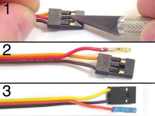 Figure 1.
Wire the Bot Board II and SSC-32 as shown in the schematic and tables in Step 3. Verify all jumpers are correct. Install the boards as shown in Figure 2 after all connections are complete and checked.
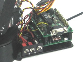 Figure 2.
Configure the Bot Board II as shown in Table 3-1. Configure the SSC-32 as shown in Table 3-2.
Bot Board II Jumpers (Table 3-1)
| Action | Setting |
|---|---|
| Connect | 6.0VDC battery to VS |
| Enable | Speaker |
| Connect | I/O 4-7 Power Bus to 5VDC |
| Connect | VL to SSC-32's VL |
Bot Board II Connections
| Pin | Function | Pin | Function |
|---|---|---|---|
| P0 | N/A | P8 | N/A |
| P1 | N/A | P9 | Speaker |
| P2 | N/A | P10 | SSC-32 RX |
| P3 | N/A | P11 | SSC-32 TX |
| P4 | N/A | P12 | PS2 Data |
| P5 | N/A | P13 | PS2 Command |
| P6 | N/A | P14 | PS2 Select |
| P7 | N/A | P15 | PS2 Clock |
SSC-32 Jumpers (Table 3-2)
| Action | Setting |
|---|---|
| Connect | 6.0VDC battery to VS |
| Connect | 9.0VDC battery to VL |
| Disconnect | VL = VS1 |
| Enable | 115.2k baud |
| Connect | VL to Bot Board's VL |
SSC-32 Servo Connections
| Pin | Function | Pin | Function |
|---|---|---|---|
| P0 | Base Rotate | P3 | Wrist |
| P1 | Shoulder | P4 | Gripper |
| P2 | Elbow | P5 | Wrist Rotate |
Schematic. Double check your connections against the schematic below. Note: if your cable colors don't match the diagram, find a complete listing here.
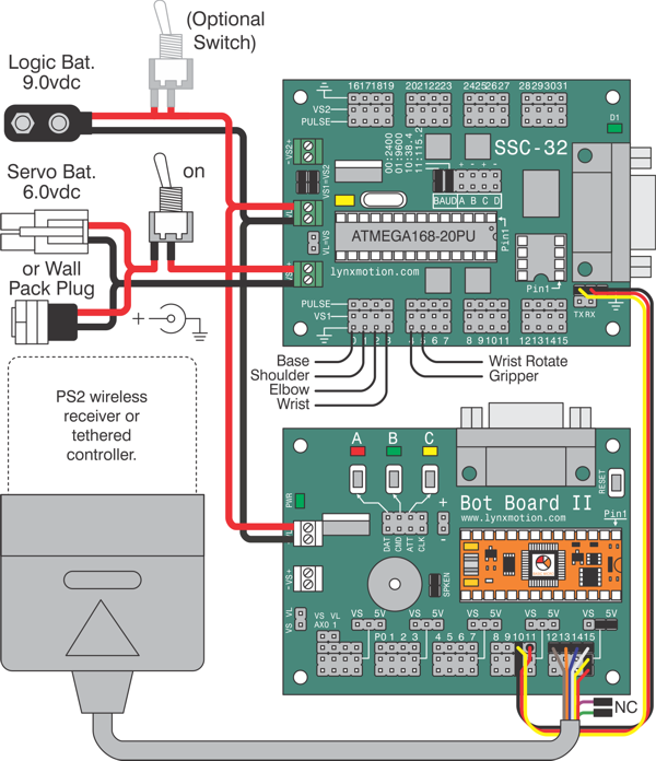
Schematic.
Download and install Basic Micro Studio. Download the arm code here. Open the .bas file and locate the arm length constants section. Remove the semicolons from in front of the arm you are using. The code defaults to AL5D — if using another arm, add a semicolon before the AL5D line. Make sure the USE_SSC32 line is not commented out (as shown in Table 4).
When finished, save your program and click "Program." Consult the serial troubleshooting guide if you have difficulties.
Table 4 — Arm Selection (SSC-32 mode)
PS2 Controls — Table 5
| Button | Function | Button | Function |
|---|---|---|---|
| L Joy Up | Gripper Up | R Joy Up | Gripper Angle Up |
| L Joy Down | Gripper Down | R Joy Down | Gripper Angle Down |
| L Joy Left | Gripper Back | R Joy Left | Base Rotate Left |
| L Joy Right | Gripper Away | R Joy Right | Base Rotate Right |
| L1 | Gripper Close | R1 | Wrist Rotate CW |
| L2 | Gripper Open | R2 | Wrist Rotate CCW |
| L3 | N/A | R3 | N/A |
| D-Pad Up | N/A | △ Triangle | Center Wrist Rotate |
| D-Pad Down | N/A | X Cross | Fully Open Gripper |
| D-Pad Left | N/A | □ Square | N/A |
| D-Pad Right | N/A | O Circle | N/A |
| Start | Enable / Disable Arm | Select | N/A |
Install the Bot Board as shown in Figure 1. Wire the Bot Board II as shown in the schematic and table in Step 2. Verify all jumpers are correct.
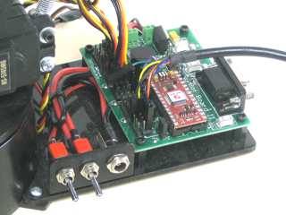 Figure 1.
Configure the Bot Board II as illustrated in Table 2.
Bot Board II Jumpers
| Action | Setting |
|---|---|
| Connect | 6.0VDC battery to VS |
| Connect | 9.0VDC battery to VL |
| Enable | Speaker |
| Connect | I/O 0-3 Power Bus to VS |
| Connect | I/O 4-7 Power Bus to VS |
| Connect | I/O 12-15 Power Bus to 5V |
Bot Board II Connections (Table 2)
| Pin | Function | Pin | Function |
|---|---|---|---|
| P0 | Base Rotate | P8 | N/A |
| P1 | Shoulder | P9 | Speaker |
| P2 | Elbow | P10 | N/A |
| P3 | Wrist | P11 | N/A |
| P4 | Gripper | P12 | PS2 Data |
| P5 | Wrist Rotate | P13 | PS2 Command |
| P6 | N/A | P14 | PS2 Select |
| P7 | N/A | P15 | PS2 Clock |
Schematic. Double check your connections against the schematic below. Note: if your cable colors don't match the diagram, find a complete listing here.
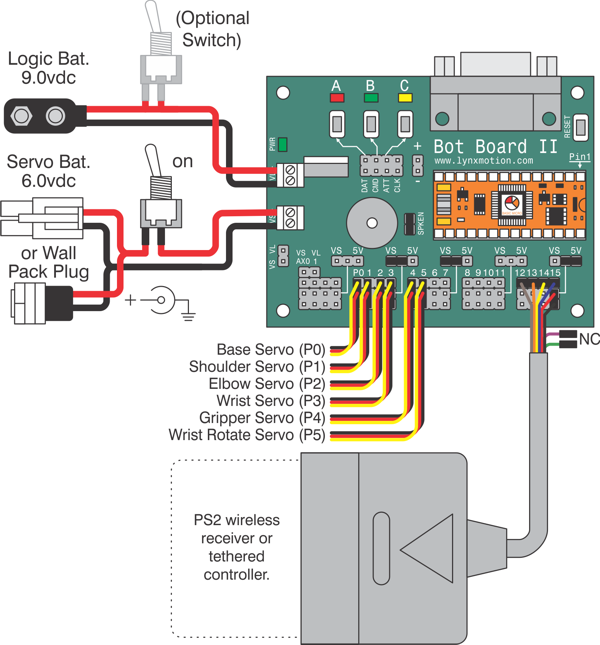
Schematic.
Download and install Basic Micro Studio. Download the arm code here. Open the .bas file and locate the arm length constants section. Remove the semicolons from in front of the arm you are using. The code defaults to AL5D — if using another arm, add a semicolon before the AL5D line. Make sure the USE_SSC32 line is commented out (as shown in Table 3).
When finished, save your program and click "Program." Consult the serial troubleshooting guide if you have difficulties.
Table 3 — Arm Selection (Bot Board only)
PS2 Controls — Table 4
| Button | Function | Button | Function |
|---|---|---|---|
| L Joy Up | Gripper Up | R Joy Up | Gripper Angle Up |
| L Joy Down | Gripper Down | R Joy Down | Gripper Angle Down |
| L Joy Left | Gripper Back | R Joy Left | Base Rotate Left |
| L Joy Right | Gripper Away | R Joy Right | Base Rotate Right |
| L1 | Gripper Close | R1 | Wrist Rotate CW |
| L2 | Gripper Open | R2 | Wrist Rotate CCW |
| L3 | N/A | R3 | N/A |
| D-Pad Up | N/A | △ Triangle | Center Wrist Rotate |
| D-Pad Down | N/A | X Cross | Fully Open Gripper |
| D-Pad Left | N/A | □ Square | N/A |
| D-Pad Right | N/A | O Circle | N/A |
| Start | Enable / Disable Arm | Select | N/A |