
AL5C Arm Assembly Instructions Rev. 1
AL5C Arm Assembly Instructions Rev. 1
Updated October 7, 2009
Safety first! Wear eye protection and never touch a powered robot!
Note: Loctite or thread locks can be used on aluminum components. Do not use on Lexan — not necessary and may cause damage.
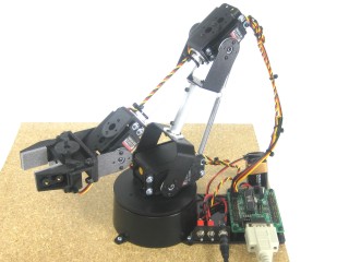
Image of complete arm.
The Lexan pieces have a protective covering that must be removed before assembly. The laser cut melts the covering into the cut edge. Gently scrape the cut edge with a flat blade screwdriver to lift and peel off. On smaller pieces, use duct tape after scraping. For further information see this page.
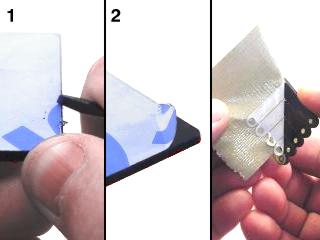 Lexan Preparation.
Attach two tubing connector hubs to the "C" and large "C" brackets using four 2-56 x .250 screws and 2-56 nuts.
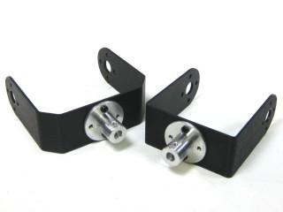 Figure 1.
Connect the hubs to the 2.25" tube using two 4-40 x .250" screws.
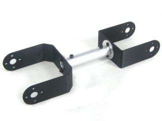 Figure 2.
Install the mechanical dampening panels as shown using four #2 tapping screws.
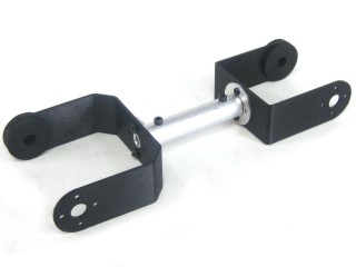 Figure 3.
Insert the 4-40 x .5" Phillips head screw through the hole in the multi-purpose bracket as shown. Secure with a steel nut.
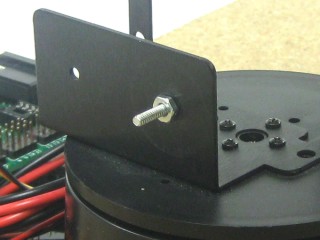 Figure 4.
Slide the large "C" bracket end over the screw and secure with a nylon insert lock nut. Start loose — tighten only if the arm wobbles. Caution: do not over-tighten! If dampeners are too tight the servo WILL heat up and CAN be damaged!
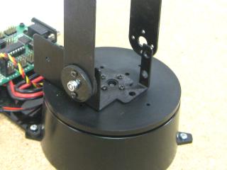 Figure 5.
Replace the black servo horn on the HS-755HB mega servo with the round nylon servo horn. Remove the screw without rotating the horn, pull it off, press the nylon horn in place as shown, and replace the screw. The arrows point to the screw holes you will use.
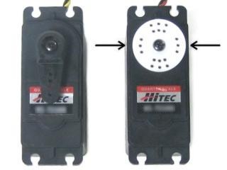 Figure 6.
Attach the HS-755HB servo to the base bracket using the 3mm hardware per the diagram below. Use two #2 x 1/4" tapping screws to secure the bracket to the servo horn. Route wires underneath the servo. Plug into channel 1 on the SSC-32. Rotate to an extreme and use a wire tie to take up cable slack.
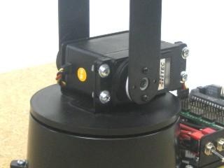 Figure 7.
Attach two tubing connector hubs to the short side of the "L" brackets using four 2-56 x .250 screws and 2-56 nuts.
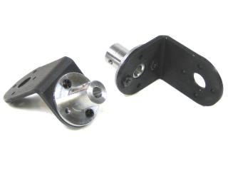 Figure 8.
Connect the hubs to the 3.38" tube using two 4-40 x .250" screws. Tighten firmly.
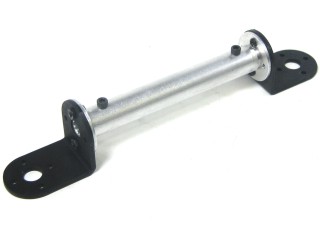 Figure 9.
Attach the tubing structure to two Multi-Purpose brackets using four 2-56 x .250 screws and 2-56 nuts.
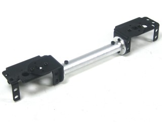 Figure 10.
Insert the 4-40 x .5" Phillips head screw through the hole in the multi-purpose bracket as shown. Secure with a steel nut.
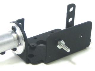 Figure 11.
Slide the screw through the dampening discs and secure with a nylon insert lock nut. Start loose — tighten only if the arm wobbles. Caution: do not over-tighten! If dampeners are too tight the servo WILL heat up and CAN be damaged!
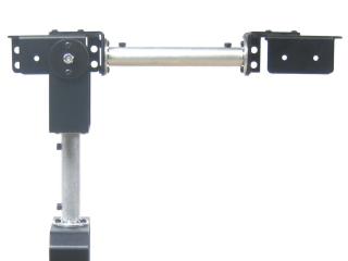 Figure 12.
Step 13: Verify the standard-size servo output horn is at center position as shown. The arrows point to the screw holes you will use.
Step 14: Attach the HS-645MG elbow servo to the bracket using the 3mm hardware per the diagram below. Use two #2 x 1/4" tapping screws to secure the bracket to the servo horn. Route wires over the servo. Plug into channel 2 on the SSC-32.
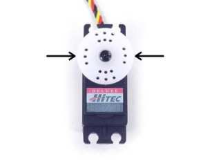 Figure 13 (servo horn centered).
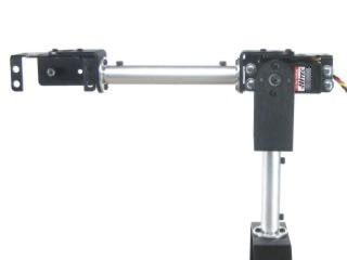 Figure 14.
Add a 6" servo extender cable to the elbow servo. Plug the cable into channel 2 on the SSC-32.
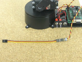 Figure 15.
Attach the Little Gripper connector to the short "C" bracket using two 2-56 x .250" screws and 2-56 nuts.
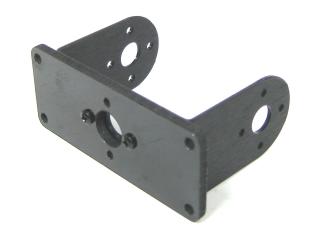 Figure 16.
Attach the short "C" bracket to the other Multi-Purpose bracket as shown. Refer to Figure 17-1 for detailed ball bearing installation.
 Figure 17-1.
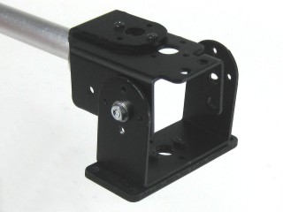 Figure 17-2.
Attach the HS-475HB wrist servo to the bracket using the 3mm hardware per the diagram below. Use two #2 x 1/4" tapping screws to secure the bracket to the servo horn. Route wires over the servo.
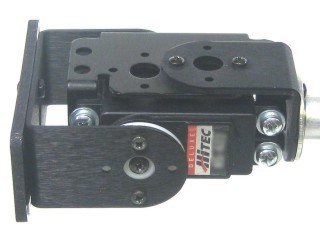 Figure 18.
Attach the Little Grip to the Lexan using three 4-40 x .375" button head screws and acorn locking nuts (three only — the gripper servo body blocks the fourth). Align the HS-422 servo to mid-position with the gripper halfway open. Remove the servo screw and horn, slide the servo in from the bottom, reseat, and replace the screw. Tighten then unscrew half a turn — too much friction can bind the servo.
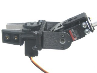 Figure 19.
Add 12" servo extender cables to both the gripper and wrist servos.
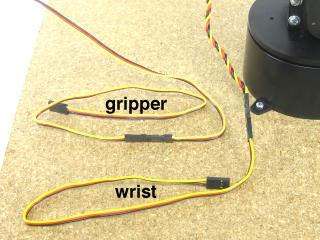 Figure 20.
Carefully bend the wrist servo back as far as it will go and use wire ties to secure the cables as shown. Leave slack in the gripper cable — do not pull too tight.
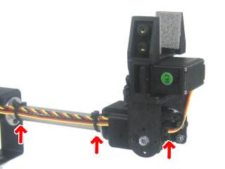 Figure 21.
Carefully stretch the arm forward as far as it will go and use wire ties to secure all cables. Leave slack — do not pull too tight. Plug the servos into the SSC-32 per Table 22.
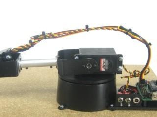 Figure 22.
SSC-32 Servo Channel Assignments (Table 22)
| SSC-32 Ch. | Servo |
|---|---|
| 00 | Base |
| 01 | Shoulder |
| 02 | Elbow |
| 03 | Wrist |
| 04 | Gripper |
| 05 | Wrist Rotate (optional) |
Step 23: Download and install LynxTerm. Connect the SSC-32 to the serial port and apply power. The green LED should light up. Run LynxTerm. Consult the serial troubleshooting guide if needed.
Step 24: Select each channel and move the servo carefully using the slider bar. Verify servos match the channels in Table 22. Real time control — be careful!
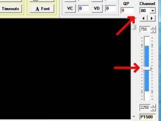 Figure 24 (LynxTerm).
Click "All = 1500" in LynxTerm. The arm should look like Figure 25. If any joint is off by more than 15°, check your assembly.
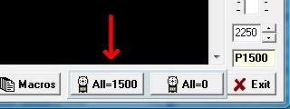
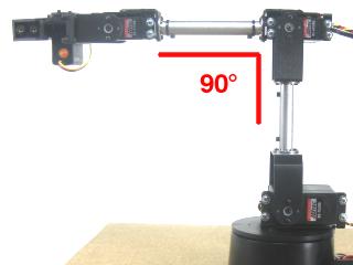 Figure 25 (target position).
Remove the servo horn screw from the elbow servo. Pull the horn off, lift the arm two clicks (30°) at the elbow, and reattach the horn and screw. Note: the Hitec spline has 24 grooves — each groove is 15°.
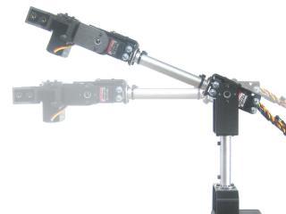 Figure 26.
Install RIOS following the on-screen prompts. The serial number is on the back of the CD sleeve. Use the RIOS Help File (Steps 1–7). Perform an accurate calibration — if the on-screen virtual arm doesn't match the real arm, calibration is inaccurate. Study the RIOS manual to learn how to store and playback sequences.
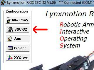 Figure 27 (RIOS).
To calibrate the arm's Shoulder servo, click the "SSC-32" button in RIOS.
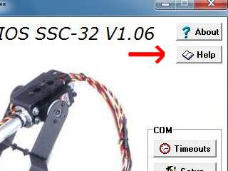 Figure 28 (RIOS).
Select Shoulder servo #2. Move the slider up (forward) until it looks like Figure 29-2. Set Min Deg to -90° and right-click to set as Min Position.
Move the slider down (backward) until it looks like Figure 29-3. Set Max Deg to 45° and right-click to set as Max Position.
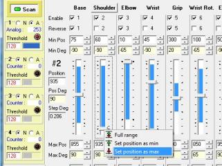 Figure 29-1 (RIOS).
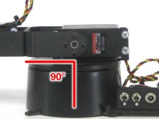 Figure 29-2 (Shoulder at -90°).
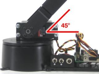 Figure 29-3 (Shoulder at 45°).
To connect springs for load-balancing, replace the servo attachment hardware in the locations shown per the diagrams below. Hook the springs together after they're secured.
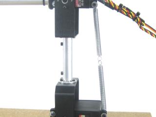 Figure 30.
The arm assembly is complete. Read and study the RIOS users guide — accessible from the Help icon on the main screen or at C:\Program Files\RIOS_SSC-32\Help.pdf.
The arm is mechanically robust but servos can be damaged by improper use — commanding an unobtainable position, crashing into itself or other objects. The elbow servo is most vulnerable as it bears the full forearm weight. Load-balancing springs reduce this load.
Important: People do not like holding heavy objects with their arms outstretched. Servo-based robot arms don't either. The most important rule: Park the arm when not in motion! When moving or at rest it is usually fine. When holding an object, do so for the minimum time required. You can always touch the servo case to check if it is getting hot.
Figure 31.