
Pneumatic Syringe Assembly Instructions
Pneumatic Syringe Assembly Instructions
Updated October 12, 2010
Safety first! Wear eye protection and never touch a powered robot!
Do not use Loctite or thread locks. They are not necessary and may damage the PVC. PVC parts have a definite good and bad side — keep the good sides facing outward.
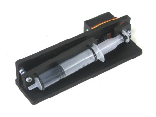
Completed assembly.
DO NOT overtighten screws on the PVC parts! The PVC will compress and will become weaker as a result!
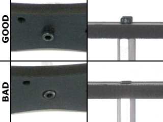 Example image.
The PVC parts are brushed off before packaging, but there may still be residue. Take a damp rag and wipe the parts clean.
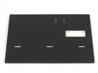 Figure 1.
Carefully cut the PVC parts out of the panel using a thin, flat blade exacto knife. Simply cut through the tabs to remove the parts. The tabs may leave rough edges — sand these smooth with sandpaper.
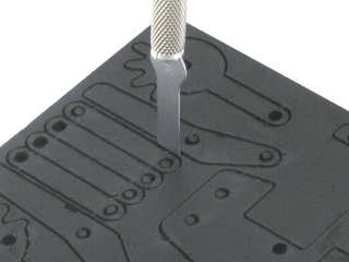 Figure 2.
Take the two large PVC parts and insert the tabbed part into the slotted one to form an "L" shape with the engraved writing on the inside. Run a bead of superglue down the seam where the two parts meet. Let dry for 3–5 minutes before proceeding.
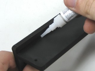 Figure 3.
Attach the 4-40 x 1.0" screw and two nylon insert lock nuts as shown. There should be a small space between the two nuts.
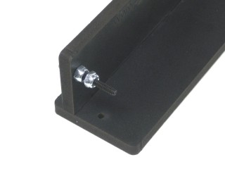 Figure 4.
Remove the screw in the center of the servo horn and remove the horn. Save this screw — you will need it in Step 9!
Install the servo into the base as shown using two 4-40 x .5" screws and 4-40 nuts. Refer to Figure 5-1 for the mounting diagram.
Figure 5-1 — Servo mounting diagram.
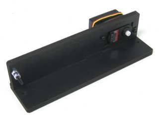 Figure 5-2.
Attach the remaining two PVC parts to the syringe using zip ties exactly as shown. Do not tighten too much — it will distort the cylinder and prevent a good seal with the plunger.
Important: the zip tie on the plunger must be aligned as shown or it will collide with the red servo horn added later.
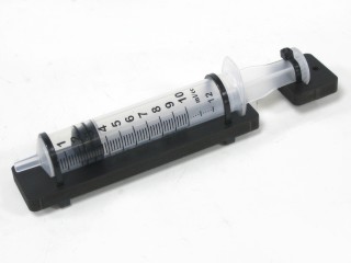 Figure 6.
Drill out the hole shown in Figure 7-2 with a .125" drill bit — this can be done by hand as shown in Figure 7-1. Afterwards, cut off the three other legs from the servo horn using angle cutters.
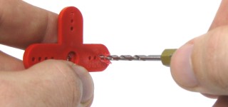 Figure 7-1 (drilling by hand).
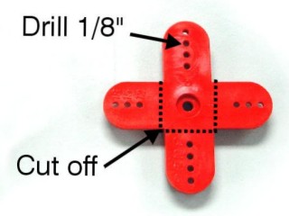 Figure 7-2 (hole location).
Attach the servo horn to the small PVC part using a 4-40 x .625" screw and two nylon insert lock nuts. Keep the assembly loose enough to allow easy movement.
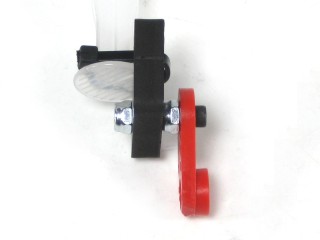 Figure 8.
If mounting the vacuum assembly to a surface (e.g. wood), do that before attaching the syringe — the syringe will block one of the mounting holes.
Attach the syringe assembly to the holder using a 4-40 nylon insert lock nut and the screw saved from Step 5. Ensure the red servo horn points straight up when the servo is centered — this maximises the range of motion.
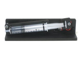 Figure 9.
Attach the elbow fitting to the long "C" bracket using two large washers and a nut. Align the fitting as shown.
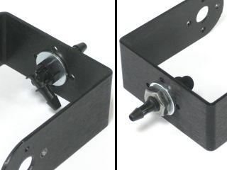 Figure 10.
Remove the old gripper, short "C" bracket, and gripper servo as shown. Leave the ball bearing in place. Save the two #2 x .250" tapping screws — you will need them in Step 12.
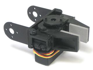 Figure 11.
Attach the long "C" bracket onto the end of the arm where the old gripper assembly was, using the two screws saved from Step 11.
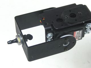 Figure 12.
Slide the suction cup over the outside of the elbow and slide the tubing over the other end. Secure the tubing to the arm with a zip tie as shown in Figure 13-1. Do NOT overtighten the zip tie — it will compress the tubing and block airflow.
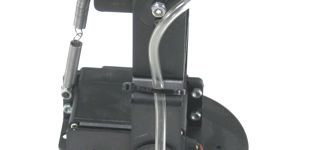 Figure 13-1 (tube location).
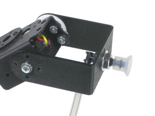 Figure 13-2.
Slide the other end of the tubing onto the end of the syringe. Plug the vacuum servo into the same servo pin as the gripper — pin 4 by default.
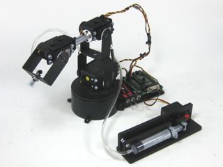 Figure 14.