
BRAT Biped Mech PS2 Tutorial
PS2 Biped BRAT Mech Tutorial
Updated December 20, 2011
Safety first! Wear eye protection and never touch a powered robot!
Hardware required: Bot Board II, BASIC Atom Pro 28, wireless PS2 controller/receiver, two PicoSwitches (DE-03).
Software & downloads:
- BASIC Micro Studio
- BRAT Servo Offset Finder Program
- PS2 Mech Control Code v1.2
Overview: This tutorial shows how to build a BRAT-based mech using the components used in this build. This is not the only approach — if you use different components you may need to modify the code and assembly instructions. Have fun and experiment!
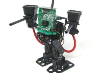
Biped BRAT Mech.
Depending on how the aluminum channel was installed on your BRAT, you may need to change it. Orient the channel as shown in Figure 1 — if yours differs, you will need to rebuild it.
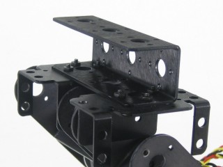 Figure 1.
After rebuilding, make sure your robot matches Figure 2 before proceeding to Step 3.
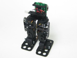 Figure 2.
Attach an ASB-24 bracket to the aluminum channel as shown using 2-56 screws and nuts. The bracket will be off-centre, but the servo horn will be centre-aligned.
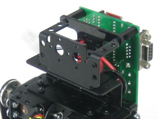 Figure 3.
Attach a suitable servo to the ASB-24 — an HS-645 is recommended. In testing, the turret was unstable with HS-475 or HS-485 servos. Remove the servo horn. This servo rotates the gun platform turret. Plug it into P11 on the Bot Board II.
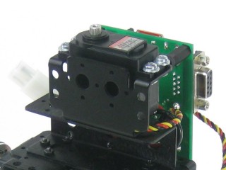 Figure 4.
The gun platform turret uses the add-on base rotate (ABR-01). A MPSH-01 supports the camera; HUB-08s attached to ASB-06s support the guns.
Use 2-56 screws and nuts to attach brackets via the innermost holes as shown. Use a 5/64" drill bit to add holes for the outermost screws. Drill carefully — ensure everything is aligned properly before drilling!
Use 2-56 screws and nuts to attach the HUB-08s to the ASB-06s.
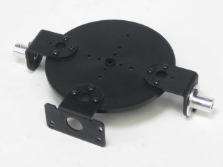 Figure 5.
Use the airsoft barrel mechanism version of the gun (NOT the IR version). If you use different guns, you may need to modify the code — the assembly instructions may not apply. Gun wiring is covered in Step 12.
Drill the centre hole of the HUB-08s to .25" to accommodate the gun mounting posts. File or cut down the ridges on the posts to fit into the HUB-08. Attach the guns to the HUB-08s using epoxy — hold or clamp firmly and allow plenty of time to set before proceeding.
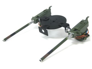 Figure 6.
Use the servo horn screw to attach the gun platform turret to the HS-645 servo. This completes the mechanical assembly. The next steps calibrate the software to the servos.
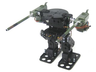 Figure 7.
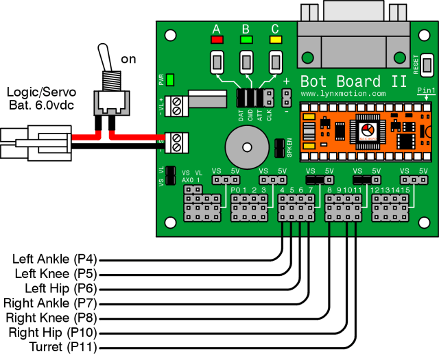
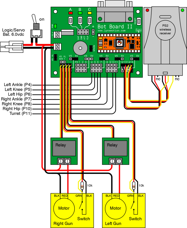
Set up the Bot Board per Table 8 and Figure 8. The buttons MUST be enabled to proceed.
| Bot Board I/O | Connection |
|---|---|
| P4 | Left Ankle |
| P5 | Left Knee |
| P6 | Left Hip |
| P7 | Right Ankle |
| P8 | Right Knee |
| P10 | Right Hip |
| P11 | Turret Rotation |
| Bot Board II Jumper Settings | |
| Enable | A, B, and C buttons |
| VS | I/O Groups 4–7 and 8–11 |
| Enable | SPKEN (Speaker Enable) |
Figure 8 — Bot Board II wiring diagram
Download and install BASIC Micro Studio. Download the BRAT Servo Offset Finder Program, load it into the IDE, and program the Atom Pro. Use the buttons to adjust:
- A — decrease servo offset by 5µs
- C — increase servo offset by 5µs
- B — change which servo is being adjusted, and save offsets (order shown in Figure 9)
If the Speaker is enabled, pressing B plays a tone that rises in pitch as you cycle through servos and drops to a longer lower tone when returning to Start.
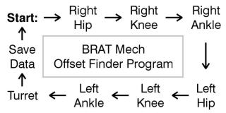 Figure 9 — Offset finder sequence.
Place the robot as close to neutral as possible and turn it on. It should hold the position resembling Figures 10-1 through 10-3. If any joint is off by more than 15°, remove the servo horn, rotate to align, and reattach. Use the A, B, and C buttons to fine-tune.
Note: HS-422 hip servos may oscillate when lifted — normal and minimal when walking. Higher voltage worsens this. HS-475, HS-485, HS-645 servos do not exhibit this effect.
After adjusting all servos to match Figures 10-1 through 10-3, pressing B saves the offset values to the Atom Pro's EEPROM.
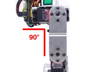 Figure 10-1 (front view).
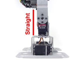 Figure 10-2 (side view).
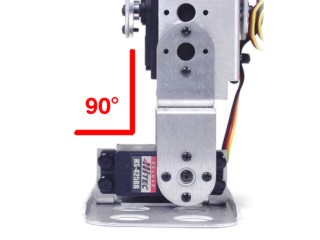 Figure 10-3 (rear view).
Download the PS2 BRAT Mech Code v1.2, load it into the IDE, and program your BRAT.
Repeat this wiring for each gun. Use heat shrink as needed. Refer to Table 12 and Figure 12 for connections.
Motor wiring: The gun's black motor wire goes directly to ground. The red wire connects to one side of the PicoSwitch; run a wire from the other side of the PicoSwitch to (+) on the Bot Board II.
Internal switch wiring: Cut a 24" servo extender cable in half and strip the ends. Strip extra length on the RED wire and solder a 10kΩ resistor onto it. Solder both the yellow wire and the other end of the resistor to one side of the switch. Solder the black wire to the other side.
| Bot Board II | Mech Component |
|---|---|
| P16 (AX0) | Right gun PicoSwitch |
| P17 (AX1) | Right gun internal switch |
| P18 (AX2) | Left gun PicoSwitch |
| P19 (AX3) | Left gun internal switch |
Figure 12 — Gun wiring diagram
The PS2 control commands are shown in Table 13. Note: the command set has changed slightly from the PS2 control tutorial — read the table carefully.
| PS2 Button | Command |
|---|---|
| Left Joystick | Walk forward/backward and turn |
| Right Joystick | Aim gun platform |
| X | Return robot to home position |
| △ | Toggle switch connected to P0 |
| L1 | Shoot with left gun |
| R1 | Shoot with right gun |
| D-pad Up | Get up from face-down position |
| D-pad Down | Get up from back-down position |
| Start | Enable/Disable standby rest mode (enabled by default) |
| Select | Change stride length |
A lightweight IP wireless camera (not 2.4GHz) is recommended — the TRENDnet TV-IP110W was used in this build. Remove the camera's outer casing to reduce weight and attach it to the MPSH-01 using double-sided foam tape. Power the camera from a 7.4VDC LiPo battery with a 5VDC switching regulator.
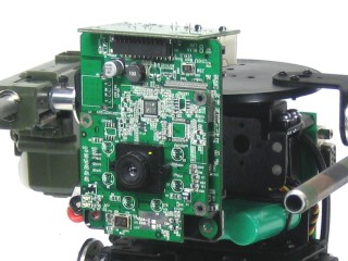 Figure 14.
There are many ways to make ammo holders. Small tupperware containers work well — cut holes to match the guns and secure them to the guns with double-sided foam tape.
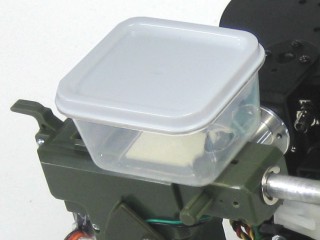 Figure 15.