
BRAT Biped SEQ Tutorial v2.01XE
Biped BRAT SEQ Tutorial (SSC-32 v2 with Register Support)
Updated March 27, 2008
Safety first! Wear eye protection and never touch a powered robot!
Note: This tutorial applies to the SSC-32 v2 with Register Support.
Software: BRAT Projects — minibipd.zip
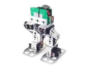
Biped BRAT.
Step 1: Download and install LynxTerm. Connect the SSC-32 to the serial port and apply power. The green LED should light. Run LynxTerm.
Step 2: Type ver and press Enter — you should see "SSC32-V2.01XE" or higher. If you have v2.01XE, test for register support: click "Reg." → "Read", enable "Initial Pulse Offset", click "Write", then "Read" again.
- If still enabled → correct version, skip to Step 4.
- If now disabled → firmware needs updating, proceed to Step 3.
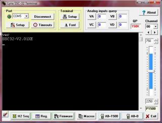 Figure 2.
Download the 2.01XE firmware. Remove power from the SSC-32 and set the baud rate to 115.2k (refer to the manual if needed). Apply power again with the SSC-32 connected to the PC. Click "Firmware" along the bottom of the LynxTerm screen, then "Open" and browse to the firmware file. Click "Begin Update".
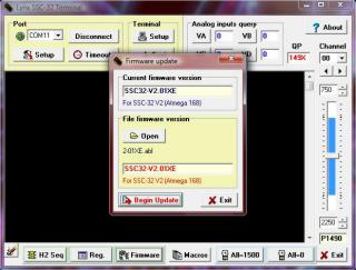 Figure 3.
When the firmware update is complete, click "OK" then "Exit". Repeat the version test: type ver and press Enter — the correct firmware version should be returned.
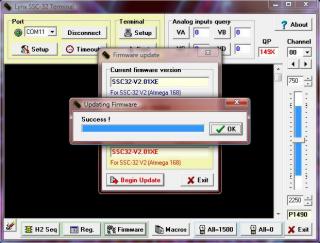 Figure 4.
Place the robot as close to neutral as possible. Click "All=1500" in the bottom right of the LynxTerm screen. The robot should go to and hold neutral, resembling Figures 5-2 and 5-3. If any joint is off by more than 15°, remove the servo horn, rotate to align, and reattach.
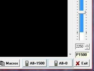 Figure 5 (LynxTerm).
 Figure 5-2 (front neutral).
 Figure 5-3 (side neutral).
From the main screen, click "Reg" to open the Registers page. Click "Default" to initialize default values.
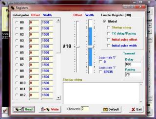 Figure 6.
Select servo #2. Adjust the Offset slider until the joint is at a perfect 90° angle. The mouse scrollwheel or keyboard arrow keys can be used for fine adjustments.
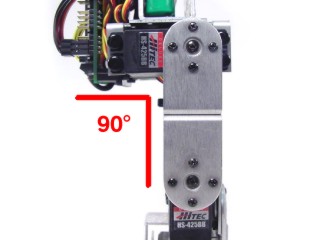 Figure 7.
Select servo #1. Adjust the Offset slider until the leg is perpendicular to the ground.
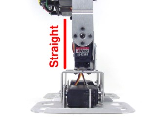 Figure 8.
Select servo #0. Adjust the Offset slider until the foot is perpendicular to the leg. Repeat the same process for the left side: servos 16 (left ankle), 17 (left knee), and 18 (left hip).
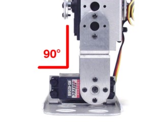 Figure 9.
Click "Write" and exit LynxTerm when complete. Optionally, check "Initial Pulse Width" to automatically enable servos on power-up — if enabled, click "Write" again to save. This completes the register configuration. From now on, the servos will be automatically aligned and/or enabled whenever the robot is turned on.
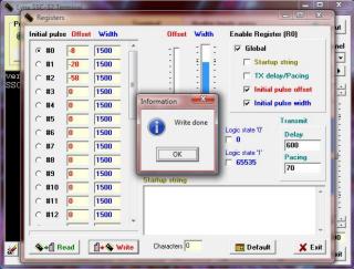 Figure 10.
Install the SSC-32 Visual Sequencer and read its manual. Run the Sequencer program. Click "SSC-32" in the upper left corner. Servo min and max positions will be defined and joint angles entered. Take time to configure accurately — sloppy configuration leads to a poorly performing robot when sharing projects.
 Figure 1.
Each servo must first be enabled by clicking its Enable checkbox. Move the servo by adjusting its slider. Enable and configure servos one at a time.
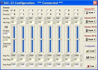 Figure 2.
Move the slider for servo 0 to 45° (Figure 3-1). Right-click and select "Set position as min" (Figure 3-2). Set "Min Deg" to −45° (Figure 3-3).
Note: Since register offsets were set in Part I, the mid-point of the slider is already the true neutral — no separate neutral step is needed here.
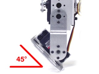 Figure 3-1.
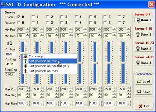 Figure 3-2 (set min).
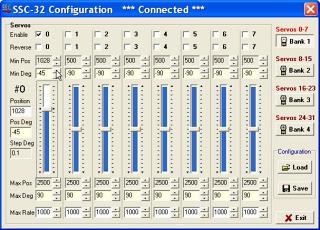 Figure 3-3 (−45° entered).
Move the slider to 84° (Figure 4-1). Right-click and select "Set position as max" (Figure 4-2). Set "Max Deg" to 84° (Figure 4-3). Return slider to 0° before proceeding.
 Figure 4-1.
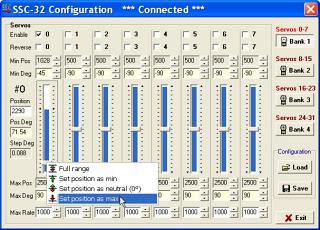 Figure 4-2 (set max).
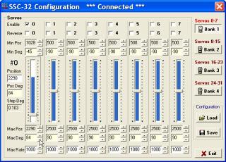 Figure 4-3 (84° entered).
Channel 1 is the right knee. Set min and max positions as shown in Figures 5-1 and 5-2. No angle adjustment is needed — the knee can reach ±90°. Return slider to 0° before continuing.
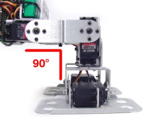 Figure 5-1 (min).
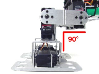 Figure 5-2 (max).
Channel 2 is the right hip. Set min (−90°) as in Figure 6-1 and max (45°) as in Figure 6-2. Knees are bent in Figure 6-2 for clarity. Return slider to 0° before continuing.
 Figure 6-1 (min −90°).
 Figure 6-2 (max 45°).
Click "Bank 3" to access channels 16–23. Channel 16 = left ankle, 17 = left knee, 18 = left hip. Configure identically to channels 0–2, but check the "Reverse" checkbox for all three left-side channels.
Set all servos to 0° (home) and save. Save as "ConfigSSC32.cfg" for a single robot, or a new name like "BipedBRAT.cfg" for multiple robots. Save in the install directory: C:\Program Files\Sequencer_SSC-32\
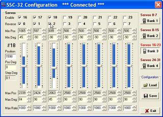 Figure 7.
Download minibipd.zip and unzip it into the SEQ install directory (default: C:\Program Files\Sequencer_SSC-32\). Click "Project" in the upper left corner.
 Figure 8.
Click "Import", select "biped6-long stride.csv", click "Open" then "OK". Enter a project name or leave the default and click "OK". You should see "Import success". Click "Exit".
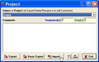 Figure 9.
Click "Sequencer" (Figure 10-1). Select "biped6-long stride" from the Project dropdown. Click "Project Loop" in the Play menu (Figure 10-3) — the robot will start moving immediately. Use Stop or Pause to halt. If both legs move the same way, check that left-side servos have Reverse enabled.
 Figure 10-1.
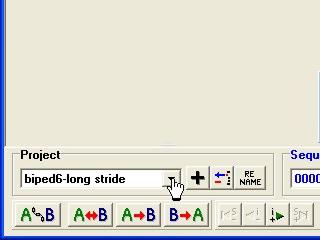 Figure 10-2.
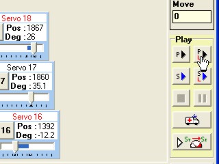 Figure 10-3.
Table 11 lists the included projects with video links where available. After getting comfortable, consult the Sequencer manual to create your own.
Run the Sequencer program. Select "empty" from the Project dropdown and click the black "+" to create a new project. Enter a name such as "BRAT-Walk".
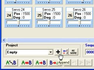 Figure 1.
Click "Swap" to clear the screen, then select servos 0, 1, 2, 16, 17, and 18.
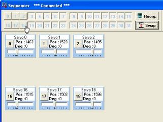 Figure 2.
Step 3: Click and drag servo boxes to match the robot's physical layout.
Step 4: Optionally click the number in a servo box to name it and change its colour.
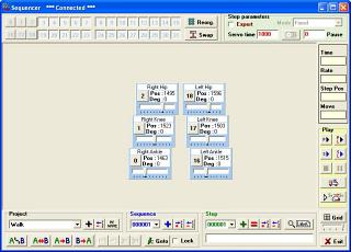 Figure 3.
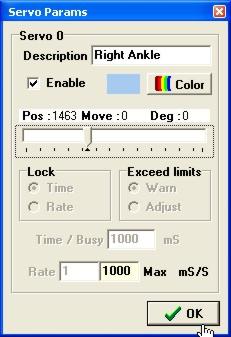 Figure 4.
Step 5 — Walking sequence: 1) Shift weight right · 2) Step forward · 3) Shift weight left · 4) Step forward. Steps 3–4 are mirror images of Steps 1–2.
Step 6 — Link servos: Click "A⟺B" and link Servo 1 with Servo 17, and Servo 2 with Servo 18. This lets you swap left and right leg positions with a few clicks.
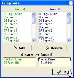 Figure 6.
Step 7: Set servos to Table 7 values (approximate). Click red "=" to overwrite Step 1.
| Ch | Deg | Ch | Deg |
|---|---|---|---|
| 2 | −25 | 18 | 25 |
| 1 | −20 | 17 | 20 |
| 0 | −8 | 16 | 8 |
Table 7.
Step 8: Click "A⟺B", deselect "Selected step", click OK, then green "+" to add Step 2.
Step 9: Swap degrees for Servos 0 and 16 to shift weight. Click green "+" to add Step 3.
Step 10: Click "A⟺B" again, deselect "Selected step", click OK, then green "+" to add Step 4.
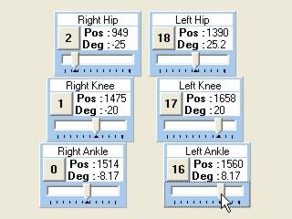 Figure 7.
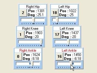 Figure 9.
Step 11: Click the sequence loop button under "Play". If the robot doesn't walk straight, increase ankle degrees to shift more weight.
Step 12: Click "Advanced Play" for speed controls.
Step 13: Use the Time slider to adjust speed — below 100% is faster, above 100% is slower. Click Loop to test, Apply to save to the project.
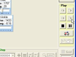 Figure 11.
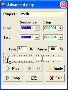 Figure 13.