
Turntable Assembly Guide v1.0
Turntable Assembly Guide v1.0
Updated December 21, 2011
Safety first! Wear eye protection and never touch a powered robot!
Insert the stainless steel pins into the plastic bearings as shown.
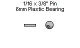
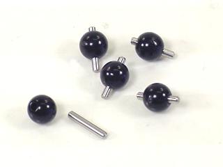 Figure 1.
Install the bearings into the base as shown. They will fit snugly.
Note, the notch in the bottom edge of the base indicates the back.
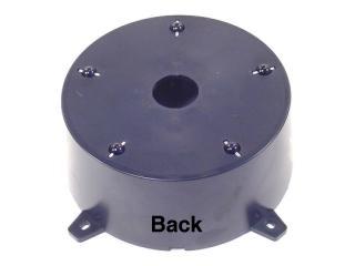 Figure 2.
Lay a piece of 400 grit sandpaper on a flat surface and move the base (upside down) in small circles on it. This will remove any imperfections on the bearings.
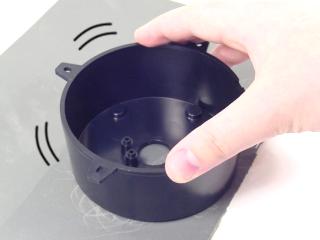 Figure 3.
Figure 4 shows the circle pattern on the sandpaper and the inset shows the bearings after any imperfections have been removed.
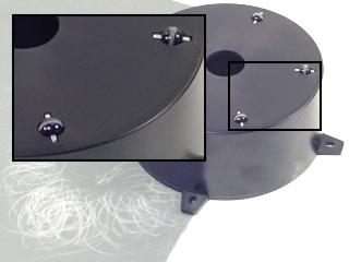 Figure 4.
Figure 5 illustrates a typical standard-size servo with its output horn (the round white part) at center position. Make sure your servo looks like the image, and then carefully remove the servo horn screw and pull the horn straight off of the servo.
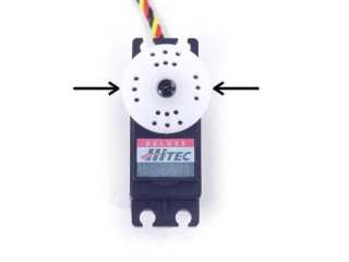 Figure 5.
Place the servo in the base as shown and screw it in tightly using four #4 tapping screws.
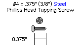
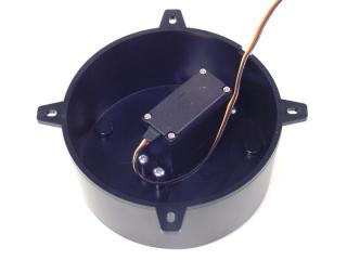 Figure 6.
Add a drop of 3-in-1 oil to each bearing.
 Figure 7.
Install the base top. The hole pattern should line up as shown in Figure 8, with one line pointing to the servo wire hole, and all of the lines pointing between the mounting tabs.
Note, this top piece is manufactured to be a tight fit. You might have to press very hard.
Attach the top with the servo horn screw.
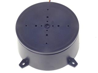 Figure 8.
Route the base servo's cable through the hole in the back of the base. This will keep the base level to the mounting surface.
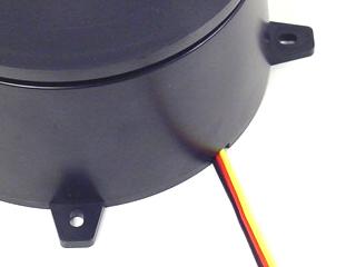 Figure 9.